CD-K7000V,CP-C7000
– 12 –
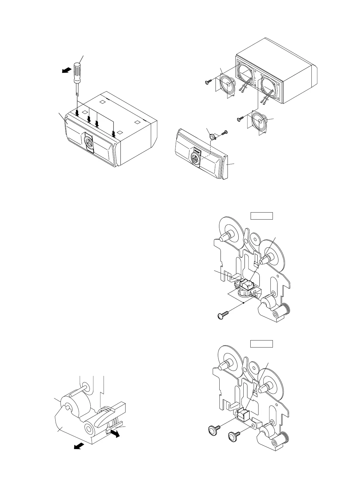
REMOVING AND REINSTALLING THE MAIN PARTS
TAPE MECHANISM SECTION
Perform steps 1 to 7 and 11 of the disassembly method to
remove the tape mechanism.
Figure 12-3
Figure 12-4
Figure 12-1
Figure 12-2
Figure 12-5
Pinch Roller
(C1)x1
<A>
Pull
<B>
Pull
Pinch
Roller
Pawl
(A1)x2
Ø2x6mm
TAPE 2
Record/Playback
Head
Erase Head
(B1)x1
Ø2x9mm
(B1)x1
Ø2x5mm
TAPE 1
Playback
Head
How to remove the record/playback and erase
heads (TAPE 2) (See Fig. 12-3)
1. When you remove the screws (A1) x 2 pcs., the recording/
playback head and three-dimensional head of the erasing
head can be removed.
How to remove the playback head (TAPE 1)
(See Fig. 12-4)
1. When you remove the screws (B1) x 2 pcs., the playback
head.
How to remove the pinch roller (TAPE 1/2)
(See Fig. 12-5)
1. Carefully bend the pinch roller pawl in the direction of the
arrow <A>, and remove the pinch roller (C1) x 1 pc., in the
direction of the arrow <B>.
Note:
When installing the pinch roller, pay attention to the spring
mounting position.
Driver should
be pried away
from speaker box.
Screwdriver
(B1)x1
Super
Tweeter
(D1)x2
ø3x10mm
(B2)x4
ø4x16mm
(C1)x4
ø4x16mm
Tweeter
Front
Panel
Mid
Range