– 63 –
CD-K7000V,CP-C7000
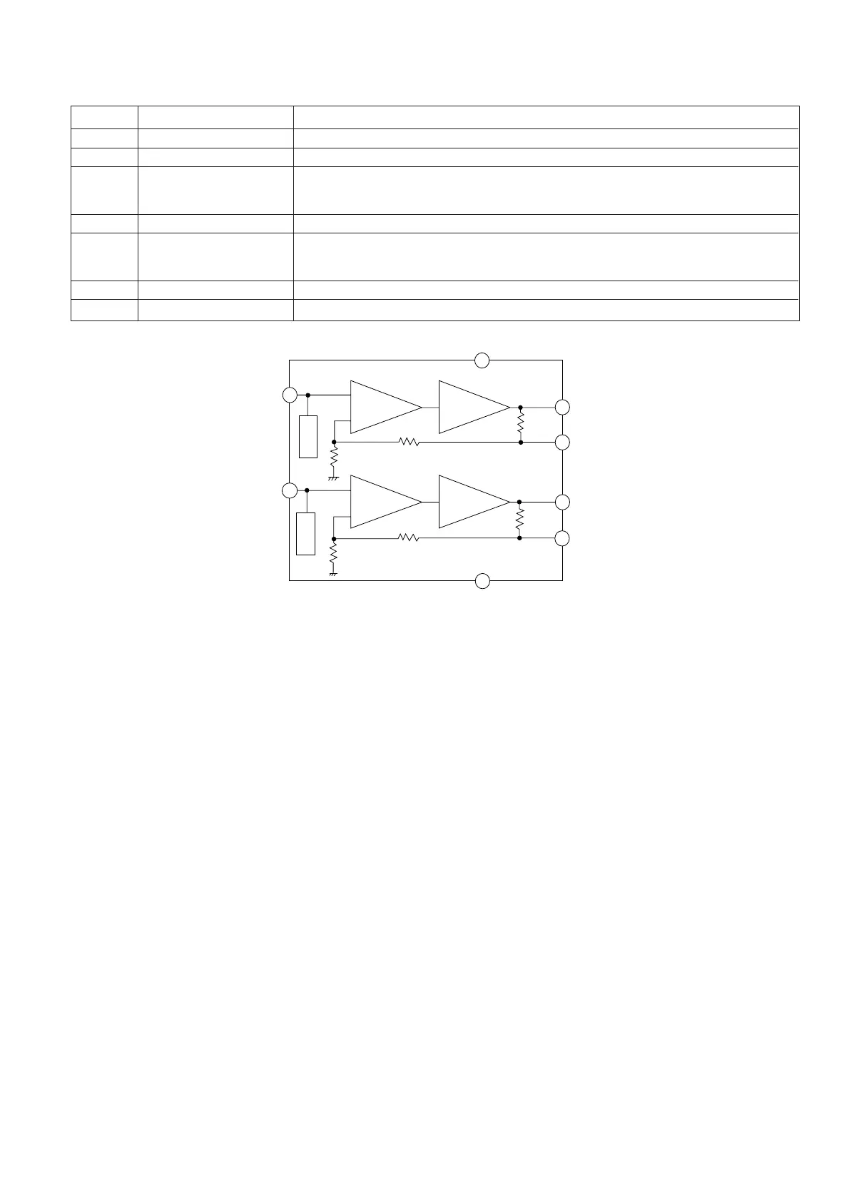
Pin No.
Terminal Name
Function
1 Clamp input terminal Input of 1.9 V clamp, 1 Vp-p composite or Y-signal
2 GND Ground
3 Sag correction terminal Able to obtain an output without any sag by feeding back the sag, generated from output
coupling C, using the external C (see block diagram).
When not using the sag correction terminal, connect directly to the pin 4.
4,5 Output terminal 6 dB amplifier output. Able to drive 75 ohms video line.
6 Sag correction terminal Able to obtain an output without any sag by feeding back the sag, generated from output
coupling C, using the external C (see block diagram).
When not using the sag correction terminal, connect directly to the pin 5.
7 V+ Power source
8 Clamp input terminal Input of 1.9 V clamp, 1 Vp-p composite or Y-signal.
ICV4 VHiNJM2267M-1: Video operation amp. (NJM2267M)
6dB
Amp
6dB
Amp
75Ω
Driver
75Ω
Driver
Vout2
75Ω
2.2Ω
2.0kΩ
Vout1
75Ω
V5AG2
V5AG1
GND
2.2kΩ
2.0kΩ
Clamp
Clamp
7
5
6
4
3
2
1
8
VIN2
VOUT2
(6dB)
VOUT2
VOUT1
(6dB)
VOUT1
V+
VIN1
Correction terminal
Correction terminal
Figure 63 BLOCK DIAGRAM OF IC