TROUBLE SHOOTING TABLE
TROUBLE SHOOTING TABLE (Continued)
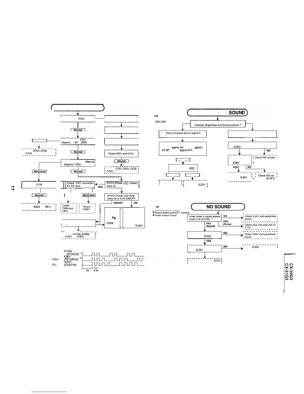
NO RASTER
I
Check
F701.
t
I
Blown out.
I
Replace the fuse.
I
1
Abnormal
1
I
Check pin (1) of
T701
voltage
(Approx. 31
OV
at 220V AC)
I
I
The fuse is again blown out.
I
I
Check
R701,
R702
and
I
;
I
D709.
---------------I
Check Secondary
Main+B
(Approx.
115V)
I
Normal
i-i
___--------_
‘-i
Abnormal
ir’
Normal
1
Check
C707,
D701,0702,
;
1
D703
and 0704.
--------------_I
1
Check
D7Or3
and 0732.
1
(
E!trF
k!L
connecto,r
lzl
~~~~~~Power
LED
Green)
1
L
NO
y
[T
1
Abnbrmal)
~---___,
r-------
I
I
Check
R609
and
R611.
{
I
_-------------
-I
oscillate ?
NO
YES
r
I
Does horizontal circuit
I+
Bus error
mode.
See
Fig.
1
or Check
IC602.
Checking the
protector circuit
(The protector
circuit still works
even if there is no
vertical waveform
at pin (2) of
IClOOl
r-
------
‘--------
I
I
Check
Q1005,
Q1006,
!
I
IC603
and
IC801.
---------,----J
If a bus error happens, the LED RED (pin 3) indicator starts flashing and the power
is turned off. The power key is still effective.
IC1003
Fig. 1 EEPROM
(ST24C02)
1
IC801
V/C/J
(TB1226CN)
-
TU201
PLL
(CXA3134)
6
uu
2s 0.5s
17-1
CIRCUITS TO BE CHECKED:
l
Tuner.
NO PICTURE, NO SOUN
l
PIF.
l
Automatic Gain Control.
l
(W),
(9V)
Power Source.
Does the noise level increase at max.
received.
No snow noise.
I
Jr
Check the tuner supply voltage MB
must be
approx,
9V.
BP must
approx.
5V.
BT
must be
approx
31V,
and
channel preset data check.
1
I
Normal
1
+
1
Check the tuner AGC.
1
I
I
Normal
1
+
1
Abnormal
[
+
Dose noise or signal appear at pin (21)
of
IC201
?
YES
Do noise or signal
appear at pin (1)
I and its related
I
of
IC801
?
1
parts.
I
r----------l
I
I
Check
IC801.
I
(
CheckANsw
1
I
I
1
circuits
(IC401).
I
I
__--------
I l----------l
------l--------L-----,
I
Check the tuner
i
I
I
I circuit.
I
l
Check
IC201.
i
I
------m-e-
t l------,---l
CIRCUITS TO BE CHECKED:
l
SIF Amplifier Circuit.
l
Sound Detector Circuit.
:
I
---------------1
(
r--------------_
Does signal appear at pins
NO
(1) and (8) of IC302 ?
+
r_--____--------
Does signal appear at pin
NO
I Check
IC302
and peripheral
r
(3) of
IC351
?
h
circuit.
I
I ---------------I
YES
r--------------_
;
Check (5) connector
IC351
;
, and peripheral circuit.
---------------I
17-2