EasyManua.ls Logo

Sharp CX-51G3 User Manual

Sharp CX-51G3
46 pages
To Next Page IconTo Next Page
Page #1 background imageLoading...
Page #1 background image
_)
CX-34G3
CX-51 G3
SHARP
SERVICE MANUAL
SX7i2CX-51
G31
CX-34G3
CX-51
G3
COLOUR TELEVISION
Chassis No.
SP-67
CX-34G3
MODELS
CX-51
G3
In the interests of user-safety (Required by safety regulations in some countries) the set should
be
restored
to its original condition and only parts identical to those specified should be used.
FEATURE
n
Reminder/ON-Off Timer
n
Blue Back Noise Mute
n English/Arabic/Chinese/French/Russian/Malay six
n
PAUSECAM
Dual System
Language
OSD
n
NTSC 4.43/3.58 MHz
(AV
only)
w Hyper Band
PLL
Tuner
n
Direct Access Remote Control
n
Wide Range Chopper Regulator System
n
NTSC Colour-Comb Filter
n
Front A/V Input Rear A/V Input/Output Terminal
n
Black Strech Circuit
CONTENTS
Y
Page
Page
l
SPECIFICATIONS
. . . . . . . . . . . . . . . . . . . . . . . . . . . . . . . . . . . . . . . . . . . . . . .
2
l
WAVE FORMS
. . . . . . . . . . . . . . . . . ..*..............................
22
l
IMPORTANT SERVICE NOTES
. . . . . . . . . . . . . . . . . . . . . . . .
2
. DESCRIPTION OF SCHEMATIC DIAGRAM
. . . . . . .
24
l
ADJUSTMENT PRECAUTIONS
. . . . . . . . . . . . . . . . . . . . . . . .
3
. BLOCK DIAGRAM
. . . . . . . . . . . . . . . . . . . . . . . . . . . . . . . . . . . . . . . . . . . .
29
l
TROUBLE SHOOTING TABLE
. . . . . . . . . . . . . . . . . . . . . . . .
17
. PRINTED WIRING BOARD ASSEMBLIES
. . . . . .
33
l SOLID STATE DEVICE BASE DIAGRAM
. . . . . . *.
19
l
REPLACEMENT PARTS LIST
. . . . . . . . . . . ..*...........
35
l
CHASSIS LAYOUT
. . . . . . . . . . . . . . . . . . . . . . . . . . . . . . . . . . . . . . . . . . .
20
WARNING
The chassis in this receiver is partially hot. Use an isolation transformer between the line cord plug and power
receptacle, when servicing this chassis. To prevent electric shock, do not remove cover. No user -serviceable
parts inside. Refer servicing to qualified service personnel.
SHARP CORPORATION
Question and Answer IconNeed help?

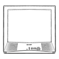
Do you have a question about the Sharp CX-51G3 and is the answer not in the manual?

Sharp CX-51G3 Specifications

General IconGeneral
BrandSharp
ModelCX-51G3
CategoryTV
LanguageEnglish

Summary

Sharp Service Manual Overview

Key Features

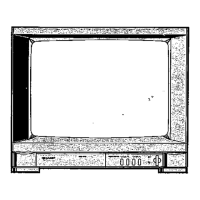
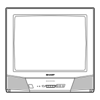
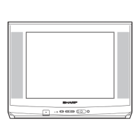
Lists the main technical features of the Colour Television models.

Important Safety Precautions

Provides critical safety warnings for servicing the television, emphasizing high voltage hazards.

Television Specifications

Important Service Notes

Guidelines for qualified personnel regarding maintenance and repair, including high voltage and X-ray precautions.

High Voltage and X-Ray Safety

Detailed precautions for servicing high voltage systems and picture tubes, including X-ray radiation.

Pre-Return Safety Checks

Final safety inspection steps before returning the receiver to the user.

Adjustment Precautions

Microprocessor Service Mode Access

Procedure for accessing the service mode using the microprocessor and remote controller.

Factory Presettings and Initialization

Details on factory presets and E²PROM initialization procedures.

Service Mode Adjustment Navigation

Diagram showing how to select different adjustment modes within the service menu.

Service Mode: Adjustment Categories

EPROM Data and Ranges

Table listing EPROM addresses, data ranges, and initial values for service adjustments.

User Adjustable Settings

List of user-configurable settings like Contrast, Colour, Brightness, and Tint.

Factory Setting for E2PROM

Channel Selection Data Initialization

Procedure to set initial channel selection data into the EPROM.

115V Adjustment Procedure

PIF Checking and Adjustment

PIF, AFT, and AGC Adjustment

VCO Adjustment

Procedure for adjusting the Voltage Controlled Oscillator.

AFT Adjustment Procedure

Steps for adjusting the Automatic Fine Tuning circuit.

RF AGC Cut-in Adjustment

Procedure for adjusting the RF Automatic Gain Control cut-in point.

Purity Adjustment

Convergence Adjustment

Static Convergence Adjustment

Procedure for static convergence adjustments using magnets.

Dynamic Convergence Adjustment

Steps for dynamic convergence adjustments on screen fringes.

CRT Cut-off, Background, and Sub-Contrast Adjustment

CRT Cut-off Service Mode (I2C Bus)

Procedure for adjusting CRT cut-off using I2C bus data in service mode.

White Balance and Background Adjustment

Steps for adjusting white balance and background color temperature.

Maximum Beam Current Check

Procedure for checking the maximum beam current.

Horizontal and Vertical Circuit Adjustments

Vertical Adjustments (50 Hz)

Details on adjusting vertical amplitude, linearity, and position for 50 Hz systems.

Focus Adjustment

Procedure for adjusting the focus of the CRT display.

PAL Chroma Adjustment

PAL Sub-Colour Adjustment (I2C Bus)

Procedure for adjusting sub-colour settings for PAL signals via I2C bus.

NTSC Chroma Adjustment

NTSC Sub-Tint Adjustment (I2C Bus)

Procedure for adjusting sub-tint settings for NTSC signals via I2C bus.

SECAM Chroma Adjustment

SECAM Black Level Adjustment (I2C Bus)

Procedure to adjust SECAM black level for R-Y and B-Y via I2C bus.

Protector Performance Checks

Beam Protector Check

Procedure to check the beam protector's functionality.

High-Voltage Protector Check

Procedure to check the high-voltage protector circuit.

Other Protector Checks

Checks for other protector circuits, like over-voltage or over-current.

AV Input and Output Checks

AV Video and Audio Output Check

Procedure to verify video and audio output signals.

AV Video and Audio Input Check

Procedure to verify video and audio input signal handling.

Video and Audio Function Checks

Video Control Function Checks

Checks for Contrast, Colour, Brightness, Tint, and Sharpness controls.

Picture Normal Mode Check

Verification of normal settings within the Picture Normal mode.

Channel Sign Display Color Check

Check for correct green display color of channel signs.

Colour System Selection Check

Sound System Selection Check

Audio Noise Mute Check

Memory Map (RH-iX2938)

Memory Map Continuation (RH-iX2938)

Memory Map Continuation (RH-iX2938)

Memory Map Continuation (RH-iX2938)

Memory Map Continuation (RH-iX2938)

Troubleshooting Table: No Raster

Troubleshooting Table: No Picture, No Sound

Troubleshooting Table: No Sound

Troubleshooting Table: Synchronization Issues

Troubleshooting Table: Vertical Linearity Issues

Troubleshooting Table: No Vertical Scan

Troubleshooting Table: No Specific Colour

Troubleshooting Table: No Colour Synchronization

Solid State Device Base Diagrams

CX-34G3 Chassis Layout

CX-51G3 Chassis Layout

Signal Waveform Diagrams

Tuner Circuit Diagram

Infrared Remote Control Unit Diagram

Schematic Diagram Description

Schematic Diagram Safety Notes

Essential safety precautions when referring to or working with schematic diagrams.

Schematic Diagram Notes

General notes regarding notation used in schematic diagrams (resistance, capacitance).

Voltage Measurement Conditions

Conditions and methods for measuring voltages in the circuit diagrams.

Waveform Measurement Conditions

Conditions and methods for measuring signal waveforms.

CX-34G3 Schematic Diagram

CX-34G3 Schematic Diagram Continuation

CX-51G3 Schematic Diagram

CX-51G3 Schematic Diagram Continuation

CX-34G3 Block Diagram

CX-34G3 Schematic Diagram Continuation

CX-51G3 Block Diagram

CX-34G3 Schematic Diagram Continuation

Printed Wiring Board Assemblies

Printed Wiring Board Assemblies Continuation

Parts List: Main Unit and Tuner

Picture Tube Parts

List of replacement parts for the picture tube assembly.

Printed Wiring Board Assemblies (Non-Replacement)

List of printed wiring boards that are not typically replaced as individual items.

Transistor Parts List

List of replacement transistors used in the main unit.

Diode Parts List

List of replacement diodes used in the main unit.

Parts List: Main Unit (Continued)

Coils and Transformers Parts List

List of replacement coils and transformers.

Controls Parts List

List of replacement control components.

Capacitors Parts List

List of replacement capacitors used in the main unit.

Parts List: Main Unit (Continued)

Resistors Parts List

List of replacement resistors used in the main unit.

Parts List: Main Unit (Continued)

Resistors Parts List Continuation

Further list of replacement resistors for the main unit.

Parts List: Main Unit (Continued)

Resistors Parts List Continuation

Final list of replacement resistors for the main unit.

Parts List: Main Unit (Continued)

Switches Parts List

List of replacement switches used in the unit.

Miscellaneous Parts List

List of various other replacement parts.

Parts List: Main Unit (Continued)

Parts List: CRT Socket Unit

CRT Socket Unit Transistors

List of replacement transistors for the CRT socket unit.

CRT Socket Unit Diodes

List of replacement diodes for the CRT socket unit.

CRT Socket Unit Coil

List of replacement coils for the CRT socket unit.

CRT Socket Unit Capacitors

List of replacement capacitors for the CRT socket unit.

CRT Socket Unit Resistors

List of replacement resistors for the CRT socket unit.

Parts List: CRT Socket Unit (Continued)

CRT Socket Unit Miscellaneous Parts

List of miscellaneous replacement parts for the CRT socket unit.

Miscellaneous Parts (Non-Replacement)

Packing Parts

List of packing materials for the product.

Supplied Accessories

List of accessories provided with the television.

Non-Replacement Accessories

List of accessories not meant for replacement.

Cabinet Parts (Model CX-34G3)

Cabinet Parts (Model CX-51G3)

Related product manuals