SECAM
CHROMA
ADJUSTMENT
lo. Adjusting point
Adjusting procedure/conditions Waveform and others
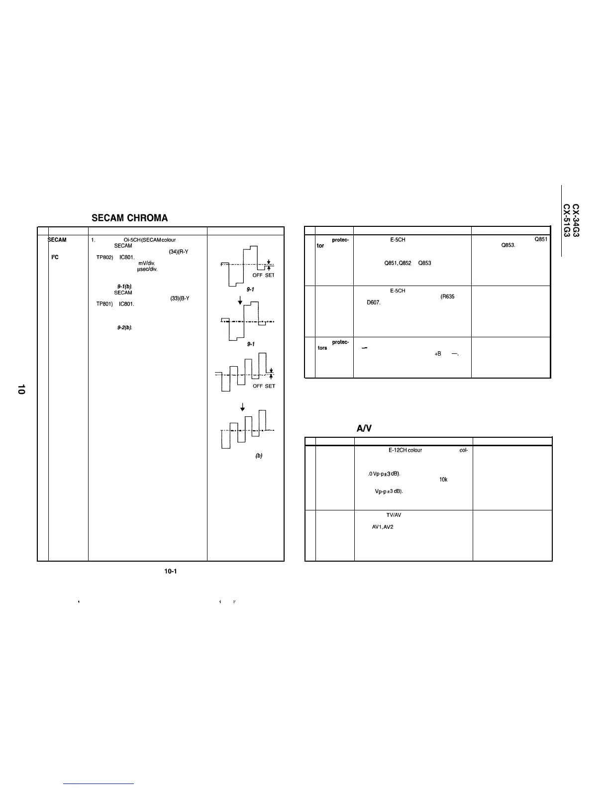
1 SECAM black
1.
Receive the
Oi-5CH
(SECAM
colour
bar) signal.
level (R-Y/B-Y)
2. Call the SECAM black level adjustment R-Y mode.
adjustment:
3. Connect the oscilloscope to pin
(34)(R-Y
OUT,
1%
bus
TP802)
of
IC801.
adjustment
l
Range
: 10
mV/div.
--
+
_
_-_-_
e-v-
-e---v
l
Sweep time : 20 psec/div. (Use a 10 : 1 probe.)
4. Adjust the R-Y data so that the offset between
1”-
OFF SET
the no-signal line and the signal line be minimum.
See Fig. 9-l(b).
5. Call the SECAM black level adjustment B-Y mode.
6. Reconnect the oscilloscope to pin (33)(B-Y OUT,
TP801) of IC801. The conditions are just the same
as in Step 3.
Fig.
9-l
(a)
4
7. Adjust the B-Y data so that the offset between
the no-signal line and the signal line be minimum.
--
7-F
_-
-_-_
_-_-_
_
_-_
See Fig.
9-2(b).
Fig.
9-l
(b)
!111
__
_-
-_
_
-- -_
_-_
OFF
S:;
Fig. 9-2 (a)
+
@
-- -- -_
_
-- -_
_
_
Fig. 9-2 (b)
10-l
e
4
iY
PROTECTOR PERFORMANCE CHECK
lo. Adjusting point
Adjusting procedure/conditions
Waveform and others
1 Beam
protec-
1. Receive the
EdCH
(monoscope pattern) signal.
l Short-circuit any of the
Q851
tor
2. Set the contrast control to maximum.
0852 and 0853.
3. Set the brightness control to maximum.
4. Make a short-circuit between the collector and
emitter of
Q851,
Q852
or
Cl853
and make sure
that the protector is activated and the stand-by
mode is called.
2 High-voltage
protector
1. Receive the
E8CH
(monoscope pattern) signal.
2. Connect the bias box to the cathode (R635 side)
of
D607.
3. Adjust the bias box voltage to 18 V and make
sure that the protector is not activated.
4. Adjust the bias box voltage to 27 V and make
sure that the protector is not activated.
3 Other
protec-
1. In checking the performance of other protectors
tors
-
for example, the one against shorting of
smoothing electrolytic capacitor of
+B
line
-,
pay
attention not to damage or deteriorate any related
element.
A/v
INPUT AND OUTPUT CHECK
lo. Adjusting point
Adjusting procedure/conditions
Waveform and others
1 Video and
1. Receive the E-12CH colour bar (100% white col-
audio output
our bar, 400 Hz, 100% modulation audio) signal.
check
2. Terminate the video output with a 75 ohm imped-
ance. Make sure the output is as specified
(1
.O
Vp-p
*3
dB).
3. Terminate the audio output with a
10k
ohm im-
pedance. Make sure the output is as specified
(1.76
Vp-p
rt3
dB).
2 Video and
audio input
check
1. Using the
TV/AV
key on the remote controller,
make sure that the modes change in the order of
TV,
AV1,
AV2
and TV again and that the video
and audio outputs are according to the input and
output terminals for each mode.
10-2