PURITY ADJUSTMENT
CONVERGENCE ADJUSTMENT
rlo.
j
Adiustins
point
j
Adiusting procedure/conditions
I
Waveform and others
Purity
adjustment
1. Using the remote controller, make the screen
colour
green-only. Adjust the contrast control to have a beam
current of about 500
f.tA
(14”)/700 pA (21”).
2.
Degauss
the cathode ray tube enough with the
degaussing coil.
Note: Follow the Job Instruction Sheet to ad-
just the magnetic field.
Vertical
Bv
: +0.030 mT (0.30 gauss)
Horizontal
Bh
: +0.020 mT (0.20 gauss)
See page 10.
3. Keep the purity magnet in the zero magnetic field
in advance. Roughly adjust the convergence.
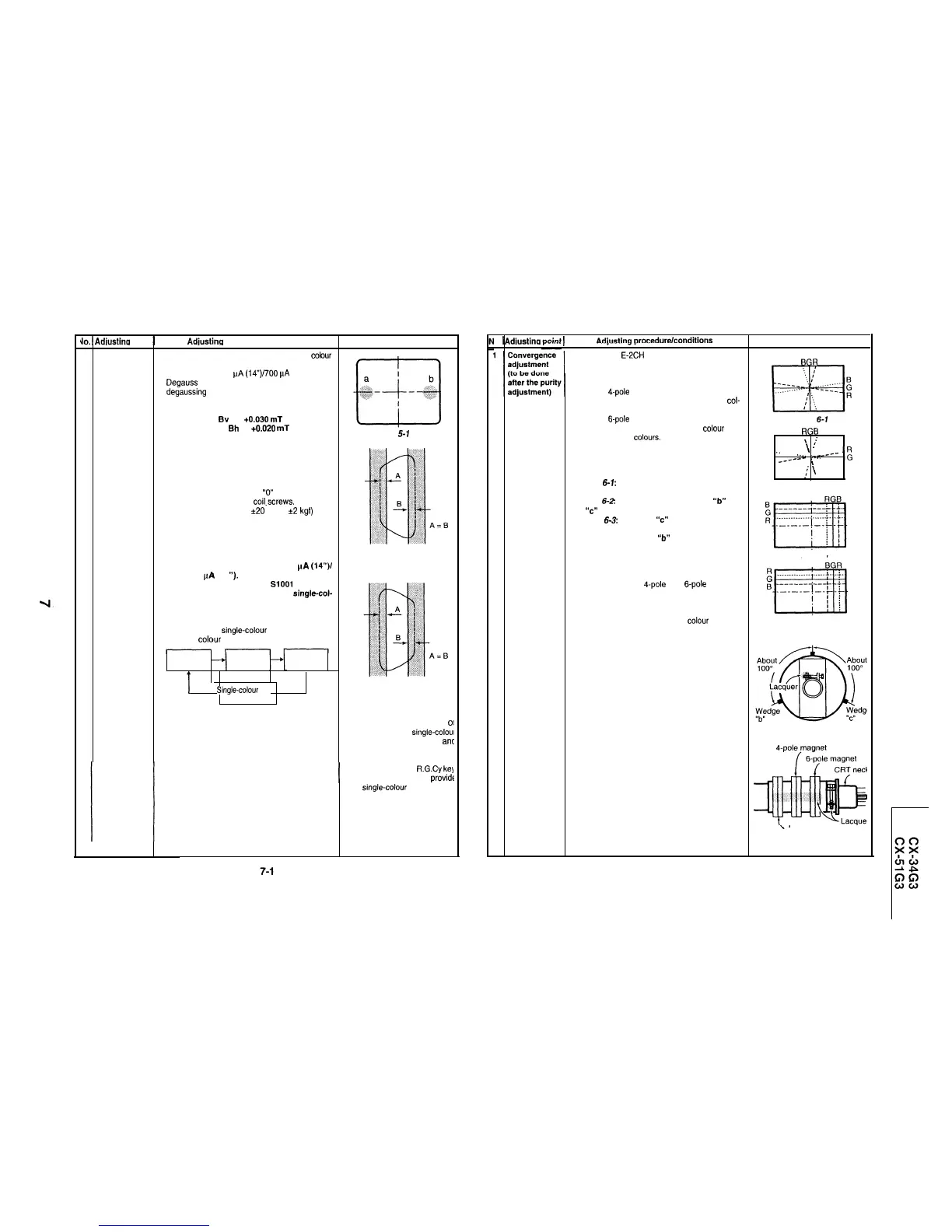
4. Observe the points “a” and “b”, as shown in
Fig.
5-1, through a microscope. Adjust the landing to
the rank “A” requirements.
5. Adjust the raster rotation to
“0”
eastward.
6. Tighten up the deflection coil.screws.
l
Tightening torque: 108
*20
N (11 lt2
kgf)
7. While observing the cathode ray tube corners.
apply the magnet sheet to have the landing at
rank “A”.
Note: Before starting this adjustment, warm
up the unit for 30 minutes or longer at
a beam current of over 500
f.rA
(14”)/
700 pA (21
I’).
Note: Set the service switch SlOOl to call the
service mode and press the
single-col-
our key on the process remote control-
ler to get the green-only screen.
l
Each time
the
single-colour key is pressed, the
screen
colour
changes as follows.
Fig.
5-l
Fig. 5-2
Rank “A” (on the
right of the CRT)
Green-only Blue-only
Red-only
screen screen
screen
T
Single-colour
Fig. 5-3
screen cleared
Rank “A” (on the
left of the CRT)
l
Whether in the service mode
OI
not, hold down the single-coloul
key for 1 second or longer
ant
the service mode is called.
The TEXT key or the R.G.Cy kel
may be used instead to
provide
the single-colour screens.
o.
j
Adiustina
j
Adiuztino
oracedurelconditions
I
Waveform and others
1. Receive the E-2CH (crosshatch pattern) signal.
I
2. Using the remote controller, call the Normal mode.
STATIC CONVERGENCE
1. Turn the
4-pole
magnet to a proper opening an-
gle in order to superimpose the blue and red col-
ours.
2. Turn the
g-pole
magnet to a proper opening an-
gle in order to superimpose the green colour over
the blue and red colours.
DYNAMIC CONVERGENCE
1. Adjust the convergence on the fringes of the
screen in the following steps.
a) Fig.
6-7:
Drive the wedge at point “a” and
swing the deflection coil upward.
b) Fig.
6-2:
Drive the wedges at points
‘lb”
and
“c”
and swing the deflection coil downward.
c) Fig.
6-3:
Drive the
“c”
wedge deeper and
swing the deflection coil rightward.
d) Fig. 6-4: Drive the
“b”
wedge deeper and
swing the deflection coil leftward.
2. Fix all the wedges on the cathode ray tube and
apply glass tape over them.
3. Apply lacquer to the deflection yoke lock screw,
magnet unit (purity, 4-pole and 6-pole magnets),
and magnet unit lock screw.
Finally receive the red-only and blue-only signals
and make sure there is no other colour mixed on
the screen.
BGR
Fig.
6-i
RGB
I
\
:
I
:
\
:
‘.
. . . . . . .
.
-
_---
_---
“-
/
. . . . . .
4
:
\
. . . . .
:
\
B
:
\
:
\
Fig. 6-2
Fig. 6-3
Fig. 6-4
Wedge “a”
Fig. 6-5
Purity magnet
fig. 6-6
7-2