CRT CUT-OFF, BACKGROUND AND SUB-CONTRAST ADJUSTMENT
00
So. Adjusting point
Adjusting procedure/conditions Waveform and others
1
CRT cut-off
1. Receive the E-5CH (monoscope pattern) signal.
l First of all, make sure that the
service mode:
2. Using the remote controller, call up the P-NORM R/G/B cut-off and B/G drive data
12C
bus data
mode. are all initial values.
adjustment
3. Turn on the service switch and select the cut-off/
background mode.
Note:
4. Set the screen control to
O/10
position.
R
CUT OFF UP
“1” KEY
5. Press the
“9”
key on the remote controller to reach
DOWN “4” KEY
the horizontal centering mode.
G CUT OFF UP
“2” KEY
6. Turn the screen control clockwise until the
hori-
DOWN “5” KEY
zontal
raster of the first glimmering
colour
be-
6
CUT OFF UP
“3”
KEY
comes slightly visible.
DOWN “6” KEY
7. Adjust the cut-off data of the other two
colours
until the horizontal raster becomes whitish.
The data can be turned up and
8. Turn the screen control counterclockwise until the
down with the above keys.
horizontal raster disappears.
(Continued)
lo. Adjusting point
Adjusting procedure/conditions
Waveform and others
2
White balance
1. Receive the E-5CH (monoscope pattern) signal.
See page 5.
and
2. Using the remote controller, call up the Video l 12300°K X: 0.273
background
Normal mode.
Y
: 0.276
service mode:
3. Connect the beam ammeter between
TP601
and
1%
bus data
TP602.
(with colour temperature meter
adjustment
4. Make sure the beam current is about 800
PA
CA-100
(MINOLTA).)
(14”)/1,100
PA
(21”).
9. Press the
“9”
key on the remote controller to call
II
12345
the NORMAL mode.
Note: Before starting this adjustment, warm
up the unit for 30 minutes or longer at
a beam current of over 500
PA
(14”)/
700
PA
(21”).
5. Adjust the G-drive and B-drive data to have a
Note:
colour
temperature of
12,300”K
(white). G-DRIVE UP
“7” KEY
6. Adjust the contrast and brightness controls to
DOWN
“-I--”
KEY
have the beam current of 200
PA.
Now check the
B-DRIVE UP
“8” KEY
background
colour.
If the
colour
temperature is DOWN
“0”
KEY
not as specified, go back to No. 1 on the preced-
ing page.
The data can be turned up and
Note: Before starting this adjustment, warm down with the above keys.
up the unit for 30 minutes or longer at a
beam current of over 500 pA (14”)/
700
pA
(21”).
iO.Using
the remote controller, call the
sub-bright-
ness
setting mode. (Receive the
E-2CH
signal.)
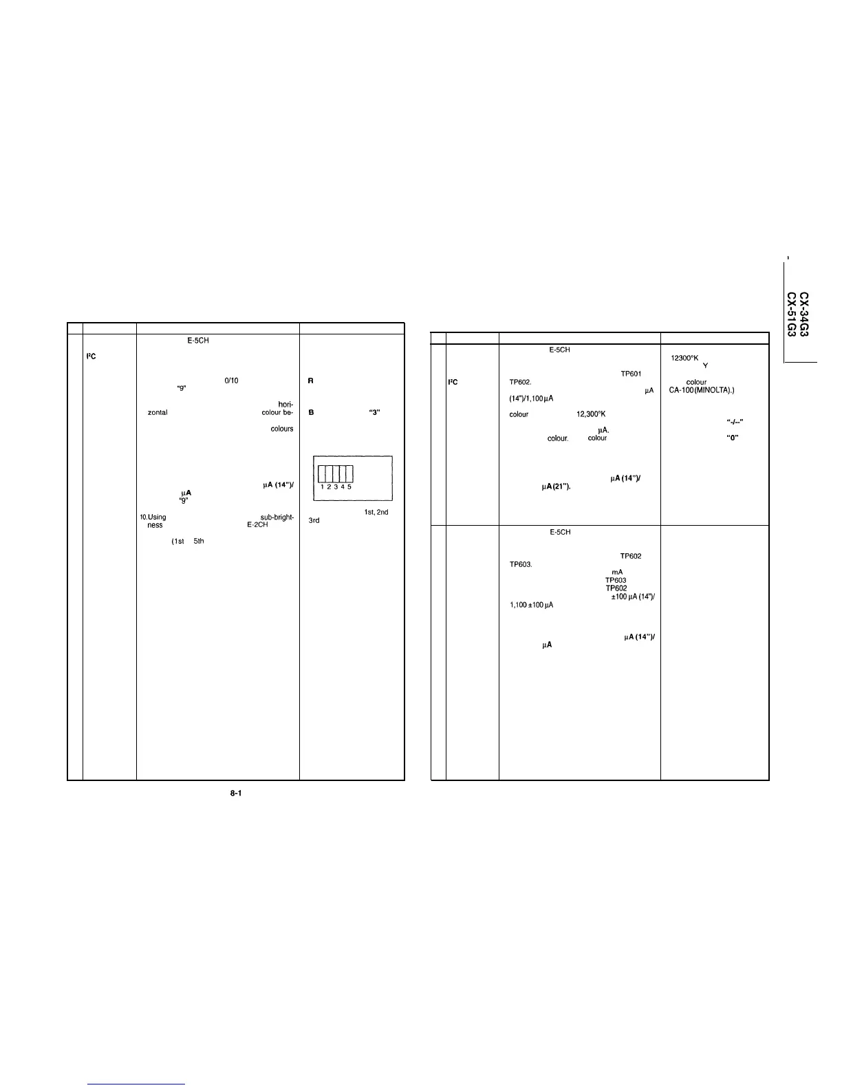
11. Set the sub-brightness data so that the third black
portion
(1st
to
5th
counted from the left of the
screen) of the window pattern looks sinking.
Note: The service mode adjustment in the
above steps 10. and 11. should be car-
ried out after the white balance and
background adjustments.
Make sure all the Ist,
2nd
and
3rd
black portions are at the
same black level.
3 Maximum
1. Receive the E-5CH (monoscope pattern) signal.
beam current
2. Using the remote controller, call up the Video
(check item)
Normal mode.
3. Connect the beam ammeter between TP602 and
TP603.
l
Ammeter’s full-scale
: 3
mA
range
l
Ammeter’s positive (+) lead : TP603
l
Ammeter’s negative (-) lead : TP602
4. Make sure the beam current is 800 *lOO
PA
(14’11
1,100*100pA
(21”).
Note: Before starting this adjustment, warm
up the unit for 30 minutes or longer at
a beam current of over 500
PA
(14”)/
700
PA
(21”).
8-1
8-2
CRT CUT-OFF, BACKGROUND AND SUB-CONTRAST ADJUSTMENT