DV-600S
DV-600H
6-2. REPLACEMENT OF MAIN PARTS
<Disassembling and assembling procedure>
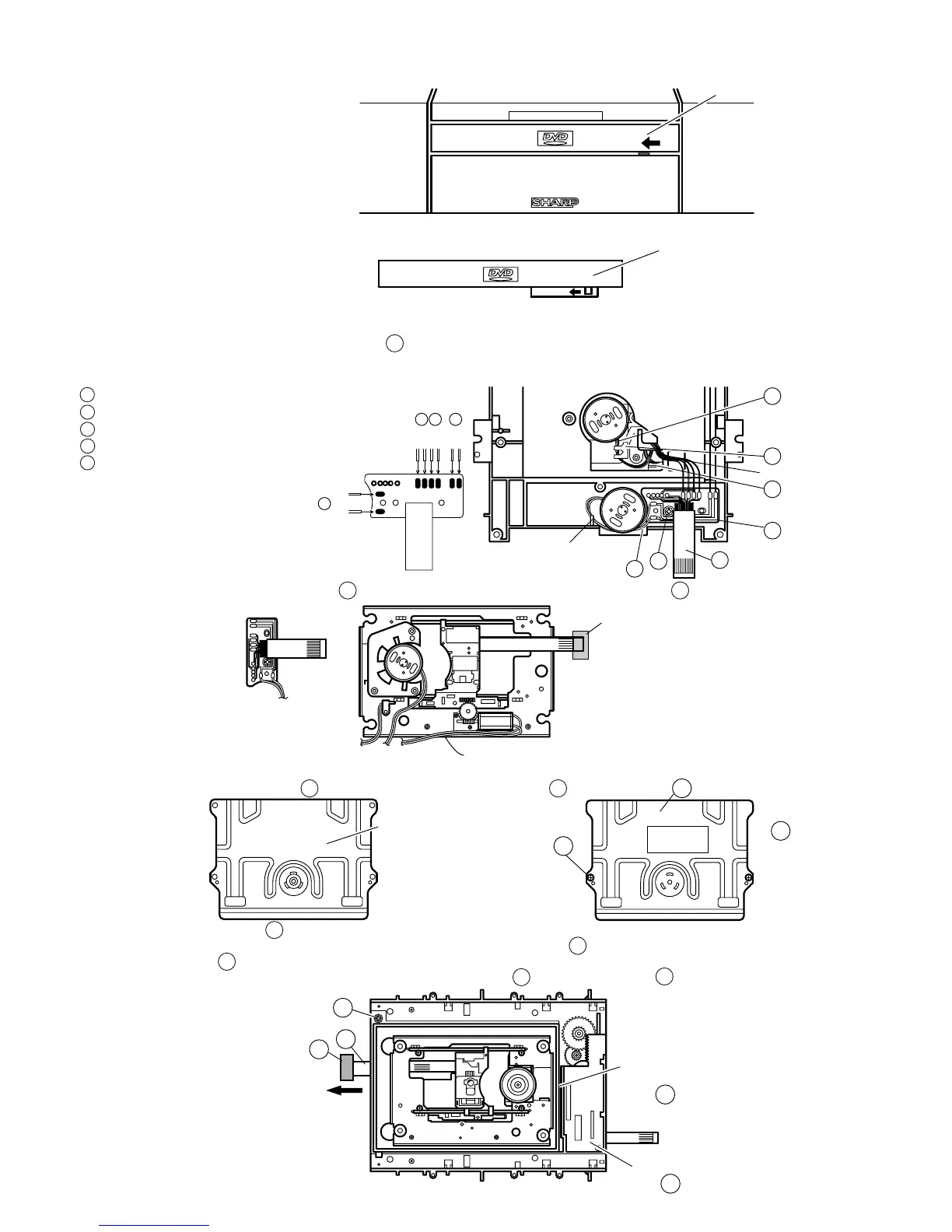
· Removing the tray (emergency ejection)
Removing the tray lock (set state)
VIDEO
Tray Decoration Panel
Insert a thin plate into the hatching part, slowly move the it in the arrow direction so that the tray is moved out a little in the arrow direction.
Note: In this state the tray cannot be removed completely.
· Drive Unit State
VIDEO
Tray Decoration Panel
Slowly move in the arrow direction, using the screwdriver having a fine head.
<Disassembling and assembling the mechanism chassis>
1. Remove the pickup FPC and loading relay FFC A from the main PWB.
Note: Fit the conductive rubber cap to the front end of pickup FPC (short-circuit).
2. Remove the solder joint of loading relay PWB at drive unit rear side.
1 Sled motor lead wire (Yellow·Orange)
2 IN SW lead wire 2 (White)
3 Spindle motor lead wire (Red·Black)
4 Loading motor lead wire (Red·Black)
5 Remove each lead wire from the claw.
1
1
2
3
4
3
2
4
A
B
C
SLmotor 1
SLmotor 2
SW
GND
SP1
SP2
L motor2
L motor2
Black
Red
Red
Black
White
White
Orange
Yellow
Remove the lead wire.
Remove the lead wire.
3. Remove the relay PWB mounting screw B (M2.6S + 6S S tight), and remove the relay PWB C .
Relay PWB
Rear side of moving chassis assembly
Conductive rubber cap
(Earth sponge)
4. Disassembling the mechanism chassis moving chassis assembly
(1) Remove the four M2.6 screws A , and remove the clamped top plate B .
P tight screw
with M2.6 washer
A
A
B
(2) Remove the M2.6 screw C .
(3) Holding aslant upward the mechanism chassis moving chassis assembly D in the arrow direction, remove.
Note: The slide rack E must be moved to the left side as shown in diagram.
Take care so that the lead wires, especially the earth sponge G at the pickup FPC F front end, must not beremoved.
Slide rack
Mechanism chassis moving
chassis assembly
P tight screw with
M2.6 washer
G
C
F
E
D
Clamper top
plate rear side
6-2