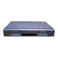
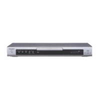
DV-600S
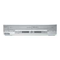
DV-600H
Pin No. Terminal name I/O Operation function
1 CVBS/Cb/B1 O Analog composite video signal output or Cb or B signal output current drive (positive)
2 CVBS/Cb/B1 O Analog composite video signal output or Cb or B signal output current drive (negative)
3 CVBS/Cb/B1 Vdd Power Supply for CVBS / Cb/B DAC1 circuit
4 Y/G 1 O Analog luminance or G signal output current drive (positive)
5 Y/G 1 O Analog luminance or G signal output current drive (negative)
6 Y/G 1Vdd Power Supply for Y/G DAC1 circuit
7 C/Cr/R 1 O Analog chrominance signal output or Cr or R signal output current drive (positive)
8 C/Cr/R 1 O Analog chrominance signal output or Cr or R signal output current drive (negative)
9 C/Cr/R 1Vdd Power Supply for C/Cr/R DAC1 circuit
10 DA Vss Ground for DAC circuit
11 Ibias 1 O Reference current for the 1st set of 3 DACs
12 VRef 1 Reference full scale voltage for the 1st set of 3 DACs
13 DA Vdd Power Supply for DACs
14 VRef 2 Reference full scale voltage for the 2nd set of 3 DACs
15 Ibias 2 O Reference current for 2nd set of the 3 DACs
16 NC No connect to pin
17 CVBS/Cb/B2 O Analog composite video signal output or Cb or B signal output current drive (positive)
18 CVBS/Cb/B2 O Analog composite video signal output or Cb or B signal output current drive (negative)
19 CVBS/Cb/B2 Vdd Power Supply for CVBS / Cb/B DAC2 circuit
20 Y/G 2 O Analog luminance or G signal output current drive (positive)
21 Y/G 2 O Analog luminance or G signal output current drive (negative)
22 Y/G Vdd Power Supply for Y/G DAC2 circuit
23 C/Cr/R 2 O Analog chrominance signal output or Cr or R signal output current drive (positive)
24 C/Cr/R 2 O Analog chrominance signal output or Cr or R signal output current drive (negative)
25 C/Cr/R 2Vdd Power Supply for C/Cr/R DAC2 circuit
26 ChipA I2C chip address select {0 : 40(hex)/41(hex) 1 : 1D(hex)/1E(hex)}
27 TEST I TEST pin (Ground)
28 DVss Ground for Digital circuit
29 CLOCK I 27MHz clock input
30 DVdd Power Supply for Digital circuit
31 Reset I Reset signal, active LOW
32 PAL/NTSC I NTSC/PAL select. This pin is sampledonly at Reset.(NTSC : Low PAL : High)
33 SO z(O) In SPI mode, serial data output / In I2C mode, grounded.
34 SDA/SI I/O(I) Serial data input, Open drain output / If SPI mode, serial data input
35 SCL/SCK I Serial clock
36 SEL I/(I) Connect to Ground / If SPI mode, this pin is chip select
37 DVdd Power supply for Digital circuit
38 DVss Ground for Digital circuit
39-46 DVIA7-0 I/O 8-bit Multiplexd Y/Cr/Cb 4:2:2 data (ITU Rec656/601) input (DVIA) or Multiplexd Y data
(ITU-Rec656/601) input in 16-bit input mode
47 Vmute I Video mute on Reset (0: normal, 1: mute)
48 C/Fsync/VBI I/O Csync/Frame sync input/output
49 F/Vsync I/O Frame sync or Vertical sync input/output
50 Hsync I/O Horizontal sync input/output
51 A/B sel I Switch control for 8-bit x 2 Mutiplexed 4:2:2 data (ITU Rec656/601) input (DVIA) or (DVIB)
52-55 DVIB7-4 I/O 8-bit Multiplexed 4:2:2 data (ITU Rec656-601) input (DVIB), or Multiplexed Cr/Cb data
(ITU Rec656/601) input in 16-bit input mode
56 DVss Ground for Digital circuit
57 DVdd Power Supply for Digital circuit
58-61 DVIB3-0 I/O Multiplexed 4:2:2 data (ITU Rec656/601) input (DVIB), or Multiplexed Cr/Cb data
(ITU Rec656/601) input in 16-bit input mode
62 TP I/O Test data input/output (Grounded)
63,64 NC No connect to pin (Ground)
11. IC FUNCTION LIST
11-1. IC201 MC44724A DIGITAL VIDEO ENCODER
11-1