29
DV-NC70/W
DV-NC70X/RU
3 Next, press the tracking button (+), (–) and change
the ATR signal waveform from max to min and from
min to max. At this time adjust the height of supply
and take-up side guide roller with the adjustment
driver (JiGDRiVERH-4) so that the ATR signal wave-
form changes nearly parallel.
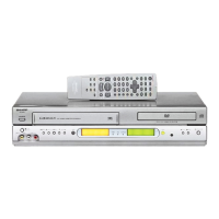
4 If the tape is lifted or sunk from the helical lead
surface, the PB ATR signal waveform appears as
shown in Figure 8-31.
5 Press the tracking button (+), (–) and make sure that
the ATR signal waveform changes nearly parallel.
6 Finally, check tape crease near the reverse guide. If
tape crease is found, adjust tilt screw 45˚ counter
clockwise. Small tape crcase will appear at retain
guide after this adjustment finished.
PB ATR
Signal
Head switching pulse
Figure 8-30.
Notes:
1. Previously set the tracking control in the center position,
and adjust the ATR signal waveform to maximum with X
value adjustment nut. Thereby the tape run rough ad-
justment is facilitated.
2. Especially the outlet side ATR signal waveform must
have higher flatness.
2. Adjustment of A/C head height and azimuth
1 Perform the initial setting of A/C head position by the
method stated in "8-17 Replacement 3".
2 Connect the oscilloscope to the audio output termi-
nal.
3 Using the alignment tape in which 1 kHz linear audio
signal has been recorded, adjust the height screw so
as to get max audio output.
4 Using the alignment tape in which 7 kHz linear audio
signal has been recorded, adjust the azimuth screw
so as to get max audio output.
5 The adjustment of 3 and 4 twice or three times
repeat, and finally adjust 4.
Figure 8-28.
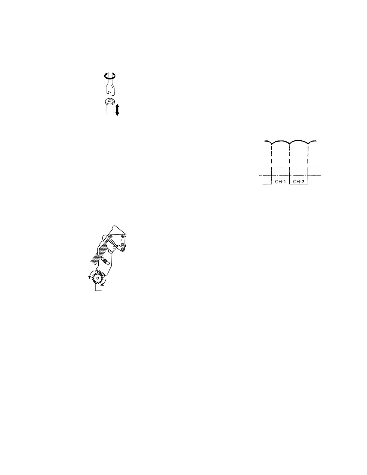
For X value adjustment
Adjust the X value, turning the gear-
type screwdriver.
Figure 8-29.
3. Tape run adjustment
1 Connect the oscilloscope to PB ATR signal output
test point, set oscilloscope sync to EXT, trigger-input
the PB CHROMA signal (head switching pulse).
2 Rough adjustment of X value
Tentatively fix A/C head arm screw 1 by the method
described in "8-17 Replacement 3".
Playback the alignment tape (VROCPSV) and
shortcircuit between TP803 and TP802 on VCR
Operation PWB. As a result the auto-tracking is
automatically cancelled, so that the X value adjust-
ment mode is set.
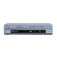
Move the A/C head with the X value adjustment gear
driver (JiGDRiVER-6) by the method shown in Fig-
ure 8-34, and adjust the A/C head so as to get the
maximum ATR signal waveform. (Note: When the A/
C head is adjusted, adjust so that the maximum ATR
signal waveform is obtained nearest the position of
initial setting made in 8-17.)