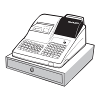
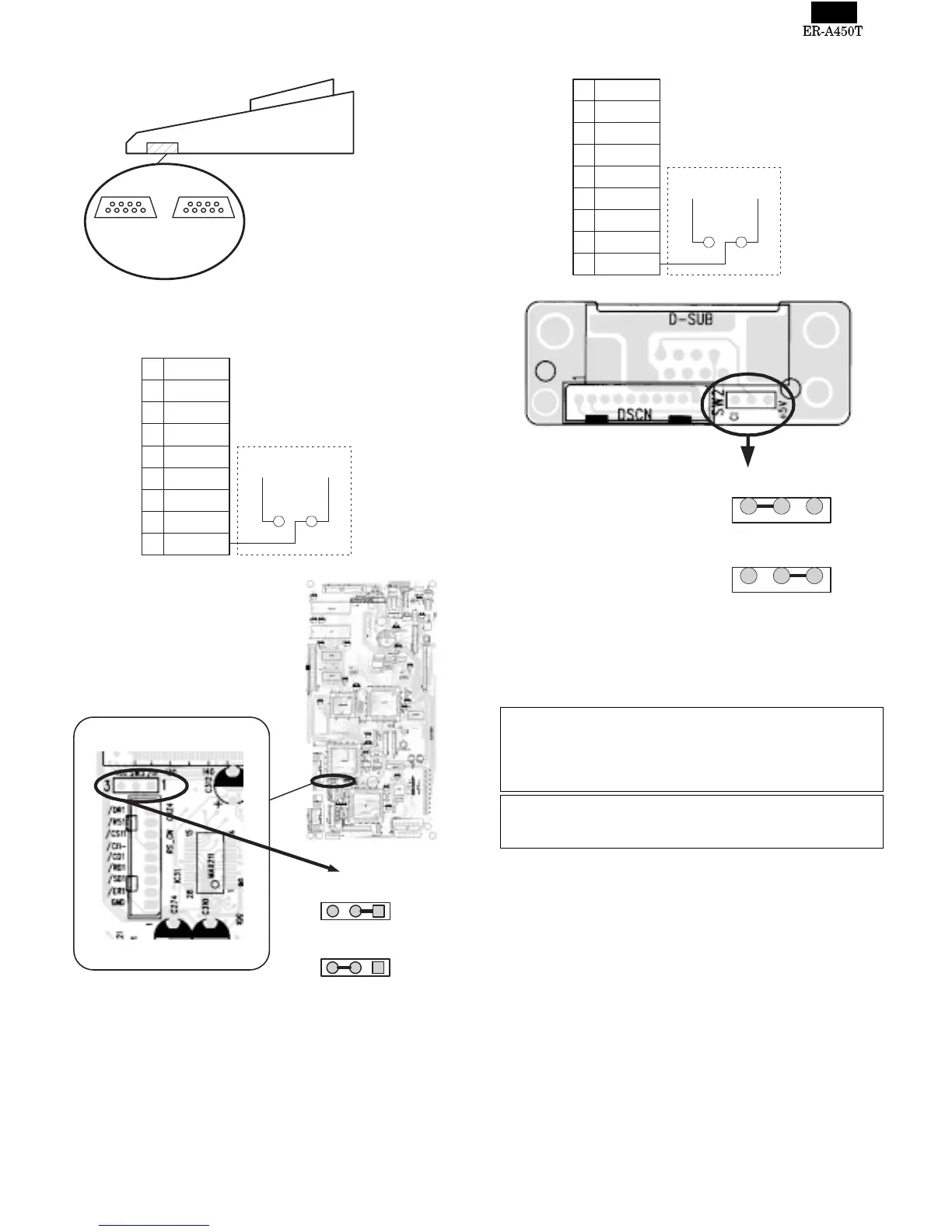
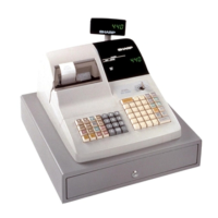
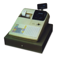
7. RS232 Interface
1) Port 2 (CH1)
2) Port 1 (CH8)
The No.9 pin signal of the Port 1 (CH8) can be selected between the
/CI signal and the +5V signal by changing the connection of the SW2
(initial value: /CI signal)
NOTE:
Optional bar code reader: When connecting an ER-A6HS1, connect
it to the Port 1 (or 2) and switch the No.9 pin signal to the +5V
signal.
When connecting other RS232 devices to either the Port 1 (or 2),
make sure the No.9 pin signal is proper before connecting the device.
If you want to connect an RS232 device to the ECR with the No.9
pin of the port 1 (or 2) set to +5V, make sure the AC cable of the
ECR is disconnected from the wall outlet to protect the device.
Channel No.:
Port 1(CH8)
Channel No.:
Port 2(CH1)
1
2
3
4
5
6
7
8
9
/CD
RD
SD
/ER
GND
/DR
/RS
/CS
/CI
VCC
SW3
on the Main PWB
Pin No.9 : /CI signal (Default)
Pin No.9 : Vcc(+5V) signal
31
SW3
VCC
/CI
31
SW3
VCC
/CI
1
2
3
4
5
6
7
8
9
/CD
RD
SD
/ER
GND
/DR
/RS
/CS
/CI
+5V
SW2
on the RS connector PWB
SW2
+5V
CI
SW2
+5V
CI
Pin No.9 : /CI signal (Default)
Pin No.9 : +5V signal
1 – 4