Introduction
Page / 4
Designs and specifications are subject to change without notice.
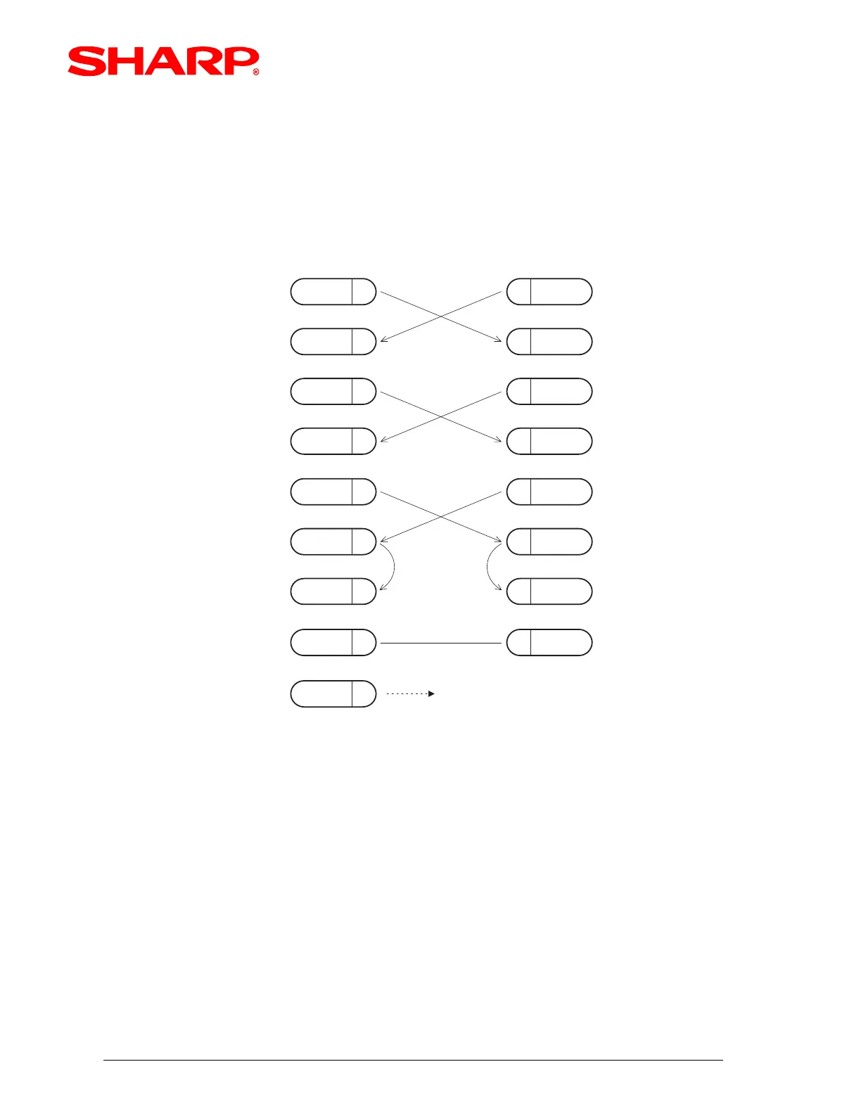
(2) ER-A450T to the ER-02FD floppy disk unit:
Please refer to (fig. 2) below for the connection pin out diagram.
SD 2 SD
RD
CTS
RD
3
6
5
3
2
6
8
ER-02FD unit
75SG
RTS
4
DCD
8
DTR
20
DSR
7
1
4
ER-A450T
CTS
SG
RTS
DCD
DTR
DSR
1FG FRAME GROUND is connected
to the shield of the cable.
25PIN D-SUB 9PIN D-SUB
SD : TRANSMITTED DATA
RD : RECEIVED DATA
DTR: DATA TERMINAL READY
DSR: DATA SET READY
RTS: REQUEST TO SEND
DCD: DATA CARRIER DETECTOR
CTS: CLEAR TO SEND
FG : FRAME GROUND
(FIG.2)