CHECKING
OF
AUDIO
CIRCUIT
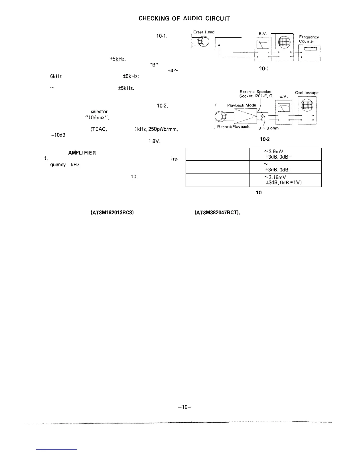
BIAS OSCILLATOR FREQUENCY CHECK
1. Make connection of instruments as shown in Fig.
IO-l.
2. Set the function selector switch to “tape” and the beat
cancel switch to “A”.
Record Mode
~
i
[aad,
k
Oscilloscope
3. Place the unit in record mode, and check that the
frequency counter reads 90
+5kHz.
Changing the beat cancel switch from “A” to
“6”
position,
see that the frequency counter reading changes by
+4
-
6kHz
from the previous value 90
25kHz:
and with the beat
cancel switch set at “C” position, see that it changes by -3
-
5kHz from previous value 90
+5kHz.
Figure
IO-I
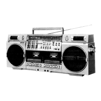
PLAYBACK AMPLIFIER SENSITIVITY CHECK
1. Make connection of instruments as shown in Fig. 10-2.
2. Set the function
selector
switch to “tape”, the volume
control knob to
“lO/max”,
and the treble/bass tone control
knob to “center” position.
Test Tape
MTT-118
3. Play a test tape
(TEAC,
MTT-118,
IkHz,
250pWb/mm,
-1OdB
prerecorded).
Head
4. See that the electronic voltmeter reads about
1.8V.
Figure
IO-2
RECORD
AMPLIFIER
SENSITIVITY CHECK
Phono input
1.99
-
3.9mV
1.
Using a CR oscillator, apply a signal of oscillation
fre-
(-50
?3dB,
OdB
=
IV)
quency
1
kHz
to each input socket of the unit.
Line input
39.8
-
79mV
2. Check for the input voltage available when the level
(-25
?3dB,
OdB
=
IV)
indicator “OVU” lights up. See Table 10.
External mic input
1.58 m
3.16mV
(-53
+3dB,
OdB
=
1V)
Table
IO
For the radio (high frequency) Circuit adjustment, refer to the GF-54542 Service Manual
(ATSM182013RCS)
or GF-5454 Service Manual
(ATSM382047RCT).