GENERAL
Power source:
(G
F-500)
(G
F-5002)
Speakers: Woofer;
Tweeter;
Output power:
(G
F-500)
(GF-5002)
Semiconductors:
(G
F-500)
(G
F-5002)
FOR A COMPLETE DESCRIPTION OF THE OPERATION OF THIS
UNIT, PLEASE REFER TO THE
OPERAT.lON
MANUAL.
SPECIFICATIONS
AC 110
-
12Ol220
-
24OV,
50/60Hz
DC 12V (Ten “D” Size batteries or
external DC supply)
AC 110
-
127/220
-
24OV,
50/60Hz
DC
12V
(UM/SUM-1,
R-20, HP-Z, or
battery
x
8, “D” or external DC
supply)
12cm
(4-3/4”)
x
2
Ceramic type
x
2
2.3 Watts per channel, minimum RMS,
at 3 ohms, from
100Hz
to
20kHz
with
no more than 10% Total harmonic dis-
tortion.
PMPO; 25W (12.5W + 12.5W)
(AC Operation)
MPO;
2ow
(low
+
low)
(AC Operation)
RMS;
IOW
(5W
+ 5W)
(DC Operation, 10% Distortion)
9-IC’s
(Integrated Circuits) + 6 Aux. IC’s
2 Transistors + 21 Aux. Transistors
58-Diodes
1 O-LED’s
15-IC’S
23 Transistors
58-Diodes
IO-LED’s
Dimensions: Width; 582mm
(22-7/g”)
Depth; 125mm
(4-I
5/16”)
Height;
202mm
(7-15/16”)
Weight (without batteries):
5.lkg
(11.3
Ibs.)
TAPE RECORDER/PLAYER
Tape: Philips-type compact cassette tape
Frequency response:
40Hz
to
16,OOOHz
(Metal tape)
S/N ratio: Deck 2
50dB (Normal tape recording)
Deck 1 55dB (Playback)
Wow and flutter: 0.06% (WRMS)
Input impedance: External Mic; 600 ohms
Phone/Line
in; 50K
ohms/20K
ohms
Output impedance:
Headphones;
8 ohms to 32 ohms
External speaker; 3 ohms to 8 ohms
Line out;
0.55Vl50K
ohms
RADIO
Frequency range:
AM; 525kHz to
1,605kHz
SW1
;
2.3MHz
to
7.3MHz
SW2
;
7.3MHz
to
22MHz
FM;
87.6MHz
to
108MHz
Specifications for this model are
orior
notice.
POWER
SUPPLY
The GF-500Z Unit will operate on an AC power supply of The GF-500 Unit will operate on an AC power supply of
11
O-
110
-
127 Volts, or 220
-
240 Volts of
50Hz
or
60Hz.
For 120 Volts, or 220
-
240 Volts of 50Hz or
60Hz.
For portable
portable use it
will
operate on its internal batteries, or from an
use it will operate on its internal batteries, or from an external
external 15 Volts DC supply (with an adaptor).
15 Volts DC supply (with an adaptor).
VOLTAGE
SELECTION
Before operating the unit on mains, check the preset voltage.
If the voltage is different from your local
vo!tage,
adjust the
voltage as follows: Slide the AC power supply socket cover by
a little loosing screw to the visible indication of the side
OF
your local
voltage.
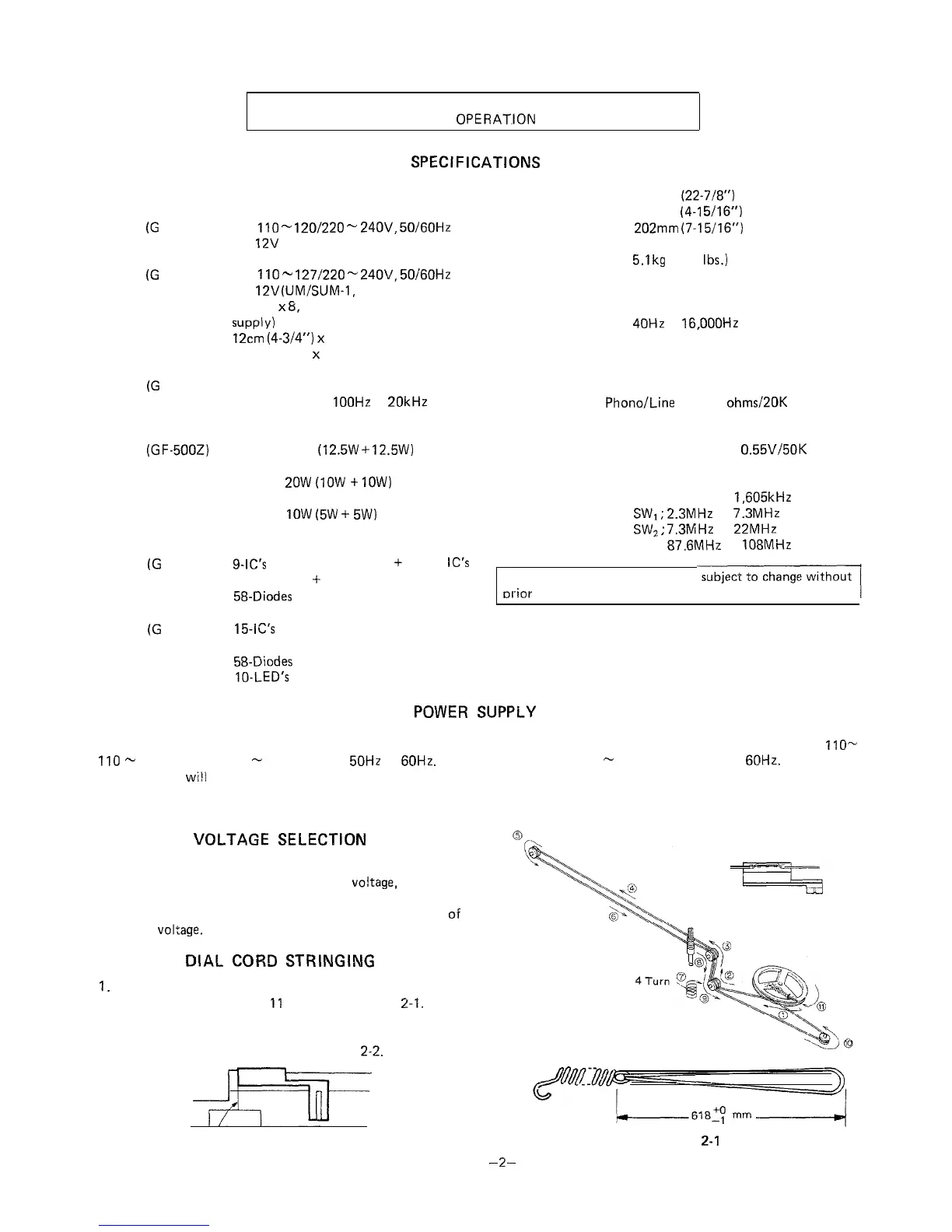
1.
2.
DIAL
CORD
STRINGING
Turn the drum fully clockwise, and set the cord in the
numerical order from 1 to
11
as shown in Figure
2-I.
Turn the tuning control knob driving shaft fully clockwise,
and adjust the dial pointer to come into “Marking-off Line”
position of the dial scale plate. See Figure
2-2.
Marking-off Line
Figure 2-2
Figure
2-I