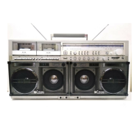
This document is a service manual for the SHARP GF-777H and GF-777E portable stereo cassette systems, providing detailed information for maintenance and repair.
The GF-777H/E is a multi-amp, 3-way, 6-speaker system designed for powerful audio output. It boasts a massive 90W PMPO (Peak Music Power Output) for the GF-777H model and 45W PMPO for the GF-777E model when operating on AC supply, delivering dynamic super woofer sound. For portable use, both models provide 24W RMS on DC supply. The speaker configuration includes two 16cm (6½") super woofers with rigid speaker rings, two 16cm (6½") woofers, and two horn tweeters for clear, crisp highs.
Technical Specifications:
- Power Source: Operates on AC 110/220/240V, 50/60Hz, or DC 15V (10 x "D" batteries or external DC supply).
- Speakers:
- Super Woofer: 16cm (6-1/2") x 2
- Woofer: 16cm (6-1/2") x 2
- Tweeter: Horn type x 2
- Output Power (DIN 45324):
- GF-777H: MPO 28W (AC), RMS 24W (DC)
- GF-777E: MPO 45W (AC), RMS 24W (DC)
- Semiconductors: 17 ICs, 52 Transistors, 1 FET, 1 SCR, 61 Diodes, 11 LEDs.
- Dimensions (W x D x H): 752mm x 166mm x 379mm
- Weight (without batteries): 12.2kg
Tape Recorder/Player:
- Tape Type: Philips-type compact cassette tape
- Frequency Response:
- Metal tape: 30Hz to 18000Hz
- CrO2 tape: 30Hz to 17000Hz
- Normal tape: 30Hz to 14000Hz
- S/N Ratio: 56dB (SNRS: ON, METAL TAPE)
- Wow and Flutter (DIN 45511): 0.14%
- Input Sensitivity/Impedance:
- Ext. Mic: 600 ohms
- Mixing Mic: 600 ohms
- Line In: 0.1V/100k ohms
- Output Level/Loaded Impedance:
- Headphones: 8 ohms to 25 ohms
- External Speaker: 4 ohms to 8 ohms
- Line Out: 0.6V/47k ohms
Radio:
- Frequency Range:
- LW: 150 - 285kHz
- MW: 520 - 1620kHz
- SW: 5.95 - 18MHz
- FM: 87.6 - 108MHz
Usage Features:
The system includes two side-by-side cassette decks for versatile record/playback, featuring soft-touch cassette controls for ease of use. It supports brilliant metal tape sound, enhancing audio quality. The Auto Program Locate Device (APLD) allows users to quickly find desired tracks. Additionally, the Sharp Super Noise Reduction System helps to minimize unwanted background noise during playback and recording.
The front panel features comprehensive controls including:
- Super Woofer Sound Controls (Left/Right)
- Deck 1 & 2 Cassette Ejection, Playback, Stop, Rewind/Review, Cut, Fast Forward Wind/Cue, Pause, and Record keys
- Deck 2 Tape Counter and Reset Button
- Stereo Recording Level Controls (Left/Right)
- Recording Mode Switch and Dubbing Switch
- VU Meter/Battery Indicator
- VU/Meter/Tuning Indicator
- Tape Selector Switches (Deck 1 & 2)
- SNRS Switch
- Meter Selector/Dial Light Switch
- FM Mode/FM Muting Switch
- Wave Band Selector Switch
- Radio Echo, Dubbing, and FM Stereo Broadcast Indicators
- Fine Tuning and Tuning Controls
- APLD Input Buttons
The top/rear panel includes:
- Power Switch and Indicator
- FM Antenna Terminals
- Input Selector Switch
- Line Output Sockets
- Record Player Input and Line Input Sockets
- Grounding Terminal
- Remote Start/Stop Control Socket
- External Microphone Socket
- AC Supply Voltage Selector
- 15 Volt DC Terminal and AC Supply Input Terminal
- Battery Compartment
- Beat Interference Cancelling Switch
- External Super Woofer Sockets and External Main Speaker Sockets
- Telescopic Antenna
Maintenance Features:
The service manual provides detailed instructions for disassembly and adjustment, ensuring the unit can be restored to its original condition using identical specified parts for user safety.
Disassembly:
- Front and Back Cabinet Removal: Involves removing various control knobs, punching metals, super woofer sound control knobs, and screws from the front and back cabinets. Antenna lead tips and a power P.W.B. socket also need to be detached.
- Main Frame Removal: Requires detaching multiple sockets from the power amplifier P.W.B., removing screws from the main frame, power switch holder, headphone/microphone P.W.B., and a socket from the echo P.W.B.
- Mechanism Block Removal: Involves detaching sockets from the mechanism P.W.B., record/playback P.W.B., and bias current P.W.B. The tape counter drive belt is detached, and screws are removed to shift and detach the mechanism block.
- Tuner Frame Removal: Requires detaching a socket from the tuner P.W.B., loosening tabs for the dial scale plate, and removing screws from the tuner frame.
- Power Amplifier P.W.B. Removal: Involves removing a screw and tabs from the super woofer sound control P.W.B., and a screw from the power amplifier P.W.B.
- Record/Playback P.W.B. Removal: Details the removal of screws and tabs from the APLD P.W.B., indicator P.W.B. holder, bias current P.W.B., input/output terminal board, and the angle supporting the volume P.W.B.
- Power P.W.B. Removal: Involves removing screws from the power transformer and AC socket.
Mechanical Adjustment:
- Pinch Roller Pressure Check: Ensures the pinch roller tension is within 300 to 380 g in play mode.
- Torque Check: Verifies that playback, fast-forward, and rewind torques are within specified ranges (35-60 gram-cm for playback, 90-135 gram-cm for fast-forward and rewind).
- Gap Check of Pinch Roller Lever: Confirms proper lever movement in play mode.
- Tape Speed Adjustment: Involves using a test tape and wow/flutter meter to adjust playback frequency to 2,985-3,015 Hz (Deck 1) and 2,970-3,000 Hz (Deck 2).
Electrical Adjustment:
- Level Meter Adjust: Adjusts VR105 and VR106.
- Battery Meter Adjust: Adjusts VR104.
- Record Amplifier Bias Current/Bias Oscillator Frequency Adjustment: Involves connecting a VTVM and oscilloscope to adjust bias oscillator frequency (76-84 kHz) and bias current (4.4 mV).
- Erase Current Check: Verifies erase current is between 135 to 185 mV.
- Record/Playback Head Azimuth Adjustment: Adjusts the head azimuth screw for maximum and in-phase sine waveform output.
- Battery Condition Meter Sensitivity Adjustment: Adjusts VR104 to ensure the battery meter pointer is at "0" when the supply voltage is 10.0 to 10.8V.
- VU Meter Sensitivity Adjustment: Adjusts VR105 or VR106 so the level meter pointer is at "0" when the VTVM indicates 0.4 mV.
- Record Amplifier Sensitivity Check: Verifies VTVM reading is 0.2mV with specified input sensitivities.
- Playback Amplifier Sensitivity Check: Confirms VTVM readings of 2.0V (external speaker), 200mV (line output), and 10mV (deck-1 monitor output).
- Record/Playback Sensitivity Check: Ensures VTVM reads approx. 1.5V after recording and playing back a 1 kHz signal.
- AM IF/RF Alignment: Detailed steps for adjusting AM IF transformers, LW/MW/SW oscillation coils and trimmers, and antenna coils.
- FM IF/RF Alignment: Detailed steps for adjusting FM IF transformers, oscillation coils, and trimmers.
- FM Stereo Alignment: Adjusts FM muting sensitivity.
- FM Stereo Indicator Lighting Level Alignment: Adjusts the semi-variable resistor for the stereo indicator.
Servicing of Leg-Less Type Resistors and Capacitors:
- Provides specific instructions for the removal and attachment of tubular-shaped and square-shaped leg-less components, emphasizing careful handling, proper soldering iron usage (with thermal control), and avoiding re-use of removed tips.
This comprehensive manual ensures that technicians have all the necessary information to diagnose, repair, and maintain the SHARP GF-777H/E stereo cassette systems to optimal performance and safety standards.