DISASSEMBl
Y
®
Caution on Disassembly
Follow
the
below-mentioned notes when disassembling
the
unit
and reassembling it, to keep its safety and excellent
performance:
1. Take cassette
tape
out
of
the
unit.
2. Be sure
to
remove
the
power supply plug from
the
wall
outlet
before starting
to
disassemble
the
unit
and remove
the
batteries from
the
unit.
3. Take off nylon bands or wire holders where
they
need
be removed when disassembling
the
unit.
After
servicing
the
unit, be sure to rearrange
the
leads where
they
were
before disassembling.
4. Take sufficient care on static electricity of integrated
circuits and
other
circuits when servicing.
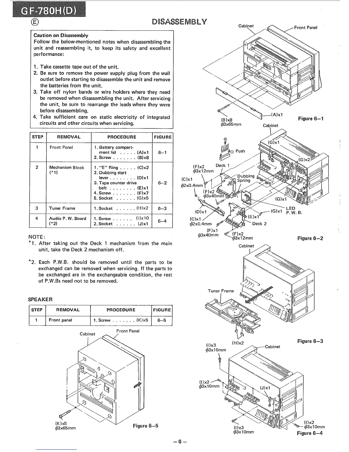
(B)x8
q'>3
x6
5mm
(A)x1
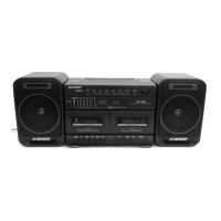
Cabinet
Figure
6-1
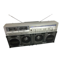
Figure
6-2
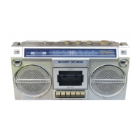
Figure
6-3
Deck 2
(H)x2
(F)x2
q'>3x12mm
®
"fIlii
~lo(j)
Push
~
.
~
//
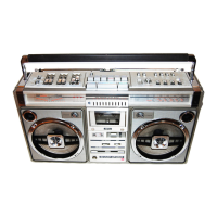
(I)x3
q'>3x10mm
(I)x3
q'>3x10mm
y
(D)x1
(C)x1
<j>2xO.4mm
(F)x1
q'>3x40mm
Front
Panel
~
~~~5mm
Figure
6-5
STEP
REMOVAL
PROCEDURE
FIGURE
1
Front
Panel
1.
Battery
compart-
ment
lid
.....
(A)x1
6-1
2. Screw
.......
(B)x8
2
Mechanism Block 1.
"E"
Ring
.....
(C)x2
(* 1)
2.
Dubbing
start
lever
........
(D)x1
3. Tape counter drive
6-2
belt
........
(E)x1
4. Screw
.......
(F)x7
5. Socket ·
.....
(G)x5
3
Tuner
Frame
1. Socket
·
.....
(H)x2
6-3
4
Audio
P. W. Board
1. Screw
......
(I)x10
6-4
(*2)
2. Socket
·
.....
(J)x1
STEP
REMOVAL
PROCEDURE
FIGURE
1
Front
panel
1. Screw
.......
(K)x5
6-5
*2.
Each P.W.B. should be removed until
the
parts to be
exchanged can be removed when servicing. If
the
parts to
be exchanged are in
the
exchangeable condition, the rest
of P.W.Bs need
not
to be removed.
NOTE:
*1.
After taking
out
the
Deck 1 mechanism from the main
unit, take
the
Deck 2 mechanism off.
SPEAKER
-6-