SERVICE
MANUAL/SERVICE.ANLElrUNG/MANUEL
DE
SERVICE
S3542GF78QHD
( )
IDOLBY SYSTEM I®
.. Noise reduction system manufactured under license
from
Dolby
Laboratories Licensing
Corporation.
"Dolby"
and the double-D
symbol are trademarks
of
Dolby
Laboratories Licensing
Corporation.
.. Geriiuschunterdruckungssystem
unter
Lizenz von
Dolby
Laboratories
Licensing
Corporaton
hergestellt. Das
Wort
"Dolby"
und das Symbol
des doppelten D sind die Warenzeichen von
Dolby
Laboratories
Licensing
Corporation.
e Reducteur de
bruits
Dolby:
Circuit
tabrique sous licence des
Dolby
Laboratories Licensing
Corporation.
Le
mot
"Dolby"
et Ie symbole
double
D sont des marques deposees des
Dolby
Laboratories
Licensing
Corporation.
.. In the interests
of
user-safety the set should be restored to its
original
condition
and
only
parts identical to those specified be
used.
.. 1m Interesse der Benutzer-Sicherheit sollte dieses Geriit wieder auf
seinen urspnlnqllchen Zustand eingestellt und
nur
die vorge-
schriebenen Teile verwendet werden .
.. Dans
l'intdret
de la securlte de
l'utlllsateur
, I'appareil devra etre
reconstitute dans sa
condition
premiere et seules des pieces
identiques acelles specifldes,
doivent
l!!tre utllisees.
Page
SCHEMATIC
DIAGRAM
..
0 0 • 0
•••••
0 •
19,20,23,24
WIRING
SIDE OF
PoW.
BOARD
..
0 • 0
21,22,25,26,27
NOTES ON SCHEMATIC
DIAGRAM
28
EQUIVALENT
CIRCUIT
(BLOCK
DIAGRAM)
OF IC 0 • 0
••••••
0
••••••••••••••
0.0
•••••
29
EXPLODED
VIEW
...
0
•••••••••••••••••
30~32
REPLACEMENT PARTS LIST
....
0
••••••••
33 ~ 40
----~~~~~~~~-INDEX
TO
CONTENTS-~~~~~~~~--...
® Page
SPECIFICATIONS 0
••••
0
••••
2
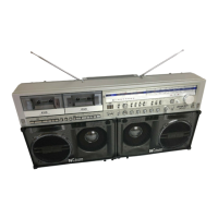
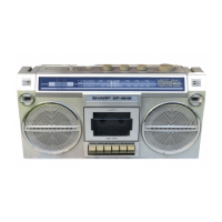
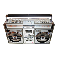
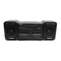
NAMES OF PARTS
0 0
••
0
•••••••••••••••••••
4
DISASSEMBLY
.....
0
•••••
0
••••••••
0
••••
o. 6
STRINGING
OF
DIAL
CORD 0
••••••
0
••••
0 • 0
••
8
VOLTAGE
SELECTION 0
••••••
0
•••••••
9
BLOCK
DIAGRAM
..
0
••••••••
0 0
••••
0
••••
9,10
MECHANICAL
ADJUSTMENT
0
•••
0 • 0 0
••
11
CIRCUIT
ADJUSTMENT
12,14,16
TEST TAPES FOR
MEASUREMENT
0
•••
0 • 0 18
INHAL
TSVERZEICHNIS
Seite
SCHEMATISCHER SCHAL
TPLAN
19,20,23,24
VERDRAHTUNGSSEITE
DER
LEITERPLATTE
21,22,25,26,27
ANMERKUNGEN
ZUM SCHEMATISCHEN
SCHAL
TPLAN
..
0
••••••••••••••••••
0 • 0
••
28
ERSATZSCHAL
TKREIS
(BLOCKSCHAL
TPLAN)
DES
INTEGRIERTEN
SCHAL
TKREISES 29
EXPLOSIONSDARSTELLUNG 0
••••
30
~
32
ERSATZTEILLlSTE
o o o.
33~40
Seite
@
TECHNISCHE
DATEN
0
••••••••
0
•••••
3
BEZEICHNUNG DER
TEILE
0
04,5
ZERLEGEN
0
••
0
••••••••
0
••••••
0 0
.6,7
SPANNEN DER SKALENSCHNUR 0
••••••••••••
, 8
SPANNUNGSWAHL
..
0
••••
0
••
0 • 0 • 0
•••
0
•••••
9
BLOCKSCHALTPLAN
0
••••••••••
9,10
MECHANISCHE
EINSTELLUNG
0
•••
0 • o. 11
SCHAL
TUNGSEINSTELLUNG
0
••••••••
0
••
12 ~ 17
TESTBANDER
FUR MESSUNG 18
®
TABLE DES
MATU~RES
Page Page
CARACTERISTIQUES
0
••••
0
••••
0
•••••••
3
DIAGRAMME
SCHEMATIQUE
19,20,23,24
NOMENCLATURE
..
0
••
0
••••••••••••
0
•••••
4,5
COTE
CABLAGE
DE
LA
PLAQUETTE
DEMONTAGE 0
•••••••••••••••
6,7
DE
MONTAGE
IMPRIME
21,22,25,26,27
PASSAGE DU CORDON DU
CADRAN
.....
:
.....
8 REMARQUES
CONCERNANT
LE
SELECTION DE
LA
TENSION 0
•••••••
0 • 0 9
DIAGRAMME
SCHEMATIQUE 0 • o. 28
DIAGRAMME
SYNOPTIQUE
9,10
CIRCUITS
EQUIVALENTS
(DIAGRAMME
REGLAGE
MECANIQUE
0
•••••••••••
0 11 SYNOPTIQUE) DE CI . 0
••••••
0
••••••••••••
29
REGLAGE DU
CIRCUIT
0
•••••••
12
~
17 VUE EN ECLATE 0
••••••••••
30
~
32
BANDESD'ESSAIPOURMESURAGE
18
L1STEDESPIECESDERECHANGE
33~40
SHARP CORPORATION