EasyManua.ls Logo

Sharp GF-320A User Manual

Sharp GF-320A
20 pages
To Next Page IconTo Next Page
Page #1 background imageLoading...
Page #1 background image
SHARI=
SERVICE
MANUAL
S2627G
F320ABK
G
F=320A(
B
K)
G
F=320A(
R)
G
F=320A(
P)
G
F-320A(Y)
G
F-320A(
B
L)
PHOTO:
GF-320A(BK)
in the interests of user-safety the set should be restored to its
original condition and only parts identical to those specified be
used.
/
INDEX
TO CONTENTS
SPECIFICATIONS . . . . . . . . .
STRINGING OF DIAL CORD . . . .
NAMES OF PARTS . . . . . . . , . . .
DISASSEMBLY . . . . . . . . . . . . . .
BLOCK DIAGRAM . . . . . . . . .
CIRCUIT ADJUSTMENT . . . . . . . .
MECHANICAL ADJUSTMENT . . . .
EXPLODED VIEW . . . . . . . . .
SCHEMATIC DIAGRAM . . . . . .
WIRING SIDE OF
P.W.BOARD
. . . .
NOTES ON SCHEMATIC DIAGRAM
TYPES OF TRANSISTOR AND LED
REPLACEMENT PARTS LIST . . . . .
.
.
,
.
.
.
.
.
.
.
.
.
.
.
.
.
.
.
.
.
.
.
.
.
.
.
.
.
.
.
.
.
.
.
r
.
.
.
.
I
.
.
.
.
,
1
.
.
.
.
.
.
.
.
.
.
.
\
.
.
.
.
.
.
.
.
.
.
.
.
.
.
.
.
.
.
.
.
.
.
.
.
.
.
.
.
.
.
.
.
.
.
.
.
.
.
.
I
.
.
.
.
.
.
.
.
Page
.
.
........
2
........
2
........
3
........
4
.
.
.
.
.
.
.
.
. . . . . . . .
5
. . . . . .
6-8
. . . . . 8
. . . . .
9,
IO
. . .
II,12
. . . . .
13,14
. . . . . . 15
. . . . . . .
15
. . . . .
16-19
SHARP
CORPORATION
Question and Answer IconNeed help?

Do you have a question about the Sharp GF-320A and is the answer not in the manual?

Sharp GF-320A Specifications

General IconGeneral
TypeBoombox
CountryJapan
ManufacturerSharp
ModelGF-320A
Speakers2
TunerAM/FM
Cassette DeckSingle
CD PlayerNo
Power SourceAC/DC
Power Output2.5W per channel

Summary

SPECIFICATIONS

General Specifications

General electrical and physical characteristics of the unit.

Radio Specifications

Radio reception frequency ranges and specifications.

Tape Recorder Specifications

Tape recorder technical specifications.

STRINGING OF DIAL CORD

NAMES OF PARTS

Component Identification

Lists and diagrams identifying various parts of the unit.

DISASSEMBLY

Disassembly Precautions

Important safety and handling notes before disassembling the unit.

BLOCK DIAGRAM

System Overview

Visual representation of the unit's internal circuitry and signal flow.

CIRCUIT ADJUSTMENT (TUNER SECTION)

AM IF/RF Adjustment Procedure

Step-by-step guide for tuning AM radio frequency adjustments.

FM IF/RF ADJUSTMENT

FM Tuning and Alignment

Procedures for adjusting FM IF and RF circuits for optimal performance.

VCO FREQUENCY ADJUSTMENT

Frequency Calibration

Steps to calibrate the Voltage Controlled Oscillator frequency.

CIRCUIT ADJUSTMENT (AUDIO SECTION)

Playback Amplifier Sensitivity

Procedure to adjust playback amplifier sensitivity.

MECHANICAL ADJUSTMENT

Tape Mechanism Adjustments

Procedures for adjusting tape drive torque, azimuth, and speed.

NOTES ON SCHEMATIC DIAGRAM

Schematic Interpretation Guide

Explains symbols, voltage measurements, and modes used in schematics.

Schematic Diagram Component Notes

Transistor and LED Types

Details on types of transistors and LEDs used in the circuit.

REPLACEMENT PARTS LIST

Parts Ordering Information

Instructions and categories for ordering replacement components.

CABINET PARTS

Cabinet Component Identification

List and identification of various cabinet parts.

ACCESSORIES AND PACKING PARTS

Accessory and Packing Component Details

List of accessories and packing materials included with the unit.

P.W.B. ASSEMBLY

Printed Circuit Board Assembly Identification

Identification of main and subsidiary printed circuit boards.
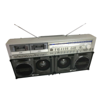
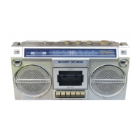
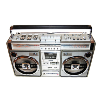
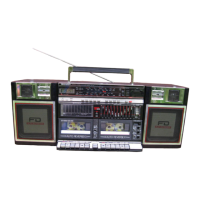
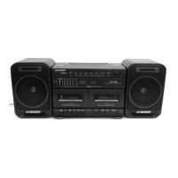
Related product manuals