NOTES
ON
SCHEMATIC
DIAGRAM
l
Resistor:
To differentiate the units of resistors, such symbol K and
M are used: the symbol
K
means 1000 ohm and the symbol
M means 1000 kohm and the resistor without any symbol is
ohm-type resistor. Besides, the one with “Fusible” is a fuse
type.
0
Capacitor:
To indicate the unit of capacitor, a symbol
P
is used: this
symbol
P
means micro-micro-farad and the unit of the
capacitor without such a symbol is microfarad. As to elec-
trolytic capacitor, the expression “capacitance/withstand
voltage” is used.
(CH), (TH), (RH), (UJ): Temperature compensation
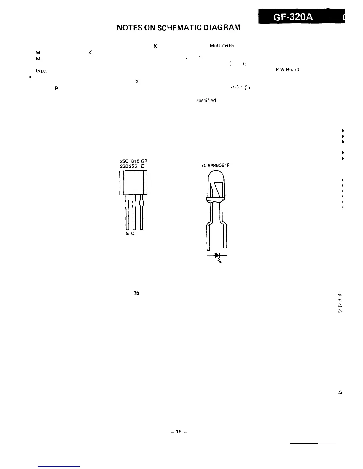
2SC1815
GR
250655
E
E
C
8
000
0
l
The indicated voltage in each section is the one measured
by Digital
Multimeter
between such a section and the
chassis with no signal given.
(
): AM mode
Marking except
for
(
):
FM
mode
. Schematic diagram and Wiring Side of P.W.Board for this
model are subject to change for improvement without
prior notice.
l
Parts marked with
”
f!L
”
(’
)
are important for main-
taining the safety of the set. Be sure to replace these parts
with
specified
ones for maintaining the safety and perfor-
mance of the set.
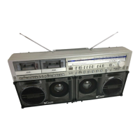
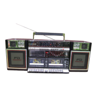
GL5PA6061F
Figure
15
TYPES OF TRANSISTORS AND LED
-15-