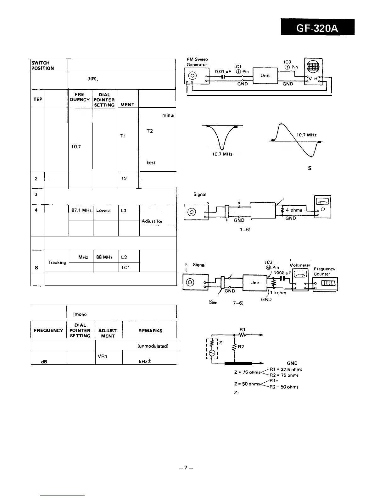
FM IF/RF ADJUSTMENT
10.7 MHz
Oscilloscope
FM mono
I
WITCH
?OSITION
SIGNAL
GENERATOR
400 Hz, 30%. FM modulated.
-
;TEP
I
1
I
1
TEST
STAGE
AD-
JUST-
MENT
Tl
REMARKS
1. Using a
minus
driver, turn
the core of
T2
counter-
clockwise
before taking
it out of the
bobbin.
2. Adjust for
best
“IF”
curve.
Adjust for best
“S” curve.
Figure 7-l FM IF
-Y-
-%f
1
IF
10
.7
MHz High
frequency
Figure 7-2 IF CURVE
Figure 7-3 FM
S
CURVE
Detection
T2
Electronic
Repeat steps 1 and 2 until no further improvement can
/
1
FM
Signal
External
Voltmeter
Rod Antenna
Generator
Speaker
t
1
I~
,(
Terminal
‘I
Unit
be made.
Band
frequency
coverage
109 MHz
Highest
TC2
maximal output.
1
frequency
Repeat steps 4 and 5 until no further improvement can
be made.
88 MHz
88MHz
L2 Adjust for
Trackmg maximal
108 MHz 108 MHz
TCl
output.
Repeat steps 7 and 8 until no further improvement can
be made.
5
Dummy
(See Figure
7-6)
6
-
7
Figure 74 FM RF
Electronic
B
FM
Signal
Generator
Rod Antenna
I
9
7
VCO FREQUENCY ADJUSTMENT
Dummy
(See
Figure
7-6)
GN/D
SIGNAL
I
400 Hz, 30%. FM modulated
GENERATOR
(mono signal)
I
Figure 7-5 VCO FREQUENCY
A
To Telescopic Rod Antenna
R2
FM mono position
98 MHz at
98 MHz
60 dB
FM stereo position (unmodulated)
VRl
Adjust for
38.00
kHz
+ 100 Hz.
To Chassis
GND
Rl
=
500hms
z
=
5o
OhmsLR2
=
5.
ohms
2:
Output impedance of signal generator
Figure 7-6 FM DUMMY
-7-