®
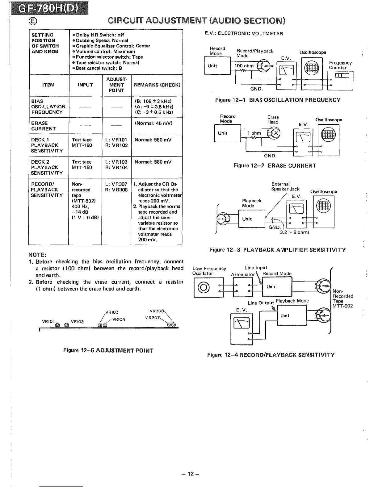
CIRCUIT ADJUSTIVIENT (AUDIO SECTION)
Figure
12-1
BIAS OSCILLATION FREQUENCY
Oscilloscope
Oscilloscope
External
Speaker Jack
E.V.
Unit
Playback
Mode
Record/Playback
Mod
Record
Mode
Unit
Erase
.
-~
BIij
GND.
Figure
12-2
ERASE CURRENT
Record
Mode
E.V.: ELECTRONIC
VOLTMETER
e
~
E.V.
Unit
!1000hm
tl~
[D
~
Frequency
Counter
I
I
-
DID
GND.
SETTING
o
Dolby
NR Switch:
off
POSITION
.. Dubbing Spood: Normal
OF SWITCH
.. Graphic Equalizer Control: Center
AND
KNOB
OIl
Volume
control:
Maximum
o Function selector switch: Tape
e Tape selector switch: Normal
.. Beat cancel switch:
13
ADJUST·
ITEM
INPUT
MENT
REMARKS
(CHECK)
POINT
BIAS
(13:
105 ± 3 kHz)
OSCILLATION
-- --
(A:
-9
±0.5
kHz!
FREQUENCY
(C:
-3
±0.5 kHz)
ERASE
--
--
(Normal: 45 mV)
CURRENT
DECK 1 Test tape L: VR101 Normal: 580 mV
PLAYBACK
MTT-l50
R:
VR102
SENSITIVITY
DECK2
Test tape
L:
VR103
Normal: 580 mV
PLAYBACK
MTT-l50
R:
VR104
SENSITIVITY
RECORD/
Non-
L:
VR307
1.
Adjust
the CR
os-
PLAYBACK
recorded R:
VR308
cillator
so
that
the
SENSITIVITY
tape electronic voltmeter
(MTT-502) reads 200 mV.
400 Hz, 2. Playback the normal
-14
dB
tape recorded and
(1
V=OdB)
adjust the semi-
variable resistor so
that
the electronic
voltmeter reads
200mV.
NOTE:
1. Before checking
the
bias oscillation frequency,
connect
a resistor
(100
ohm) between the record/playback head
and
earth.
2. Before checking the erase current,
connect
a resistor
(1 ohm) between
the
erase head and earth.
Figure
12-3
PLAYBACK AMPLIFIER SENSITIVITY
--
I-----'~..".?I
Non-
Recorded
Tape
MTT-502
Unit
Unit
Line
Output
Playback Mode
E. V.
@
Low Frequency
Oscillator
VR30~
VR307
VRI03
'~VRI04
VRIOI
19
@
VRI02
Figure
12-5
ADJUSTMENT POINT
Figure
12-4
RECORD/PLAYBACK SENSITIVITY
-12
-