Do you have a question about the Sharp GF-9696 and is the answer not in the manual?
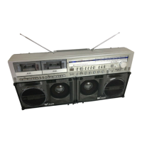
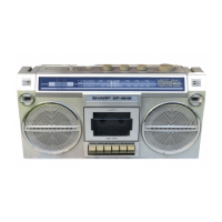
| Brand | Sharp |
|---|---|
| Model | GF-9696 |
| Category | Portable Stereo System |
| Language | English |
Procedure for removing the front cabinet and disconnecting wires.
Procedure for removing the operation panel after front cabinet removal.
Procedure for removing the dial scale plate after operation panel removal.
Procedure for removing indicator and meter P.W. boards.
Procedure for removing the mechanism block from the main P.W. Board.
Procedure for removing the front switch P.W. Board.
Procedure for removing the echo P.W. Board.
Procedure for removing the power P.W. Board.
Procedure for removing the top switch P.W. Board.
Procedure for removing the volume P.W. Board.
Procedure for removing main and audio power P.W. boards.
Explains the APLD program indicator circuit with LEDs.
Explains the muting circuit activated by APLD keys.
Describes how SNRS automatically adjusts to input signal intensity and frequency.
Details the mixing amplifier and high-pass filter stages of the SNRS circuit.
Explains the peak detector amplifier within the SNRS circuit.
Details the voltage control filter operation in the SNRS.
Procedure for adjusting flywheel thrust clearance.
Procedure for adjusting pinch roller pressure.
Checks the operation of FWD-APLD and REV-APLD mechanisms.
Instructions for measuring torque in tape playback, FF, and rewind modes.
Checks the operation of the pause mechanism.
Procedure for adjusting plunger setting position.
Procedure for adjusting tape speed.
Adjusting bias current and oscillation frequency for the record amplifier.
Procedure for checking erase current.
Checking sensitivity of the record amplifier for various inputs.
Checking sensitivity of the playback amplifier.
Checking sensitivity of the phono amplifier.
Checking sensitivity of the battery indicator LEDs.
Checking sensitivity of the level indicator.
Procedure for adjusting the record/playback head azimuth.
Schematic diagram for the APLD section.
Schematic diagram for the SNRS section.
Schematic diagram for the audio section.
Block diagram illustrating APLD function.
Block diagram illustrating SNRS function.
Block diagram illustrating power supply and control.
Wiring diagram for the main P.W. Board.
Wiring diagram for the Echo P.W. Board.
Wiring diagram for the Audio Power P.W. Board.
Equivalent circuit diagram for IC1.
Equivalent circuit diagram for IC2.
Equivalent circuit diagrams for IC101 and IC552.
Equivalent circuit diagrams for IC261 and IC262.
Equivalent circuit diagram for IC401.
Equivalent circuit diagrams for IC601 and IC602.
List of electronic components with part numbers and codes.
List of controls, filters, and transformers with part numbers.
List of mechanical parts and major assemblies with part numbers.
List of accessories, labels, and service documentation.