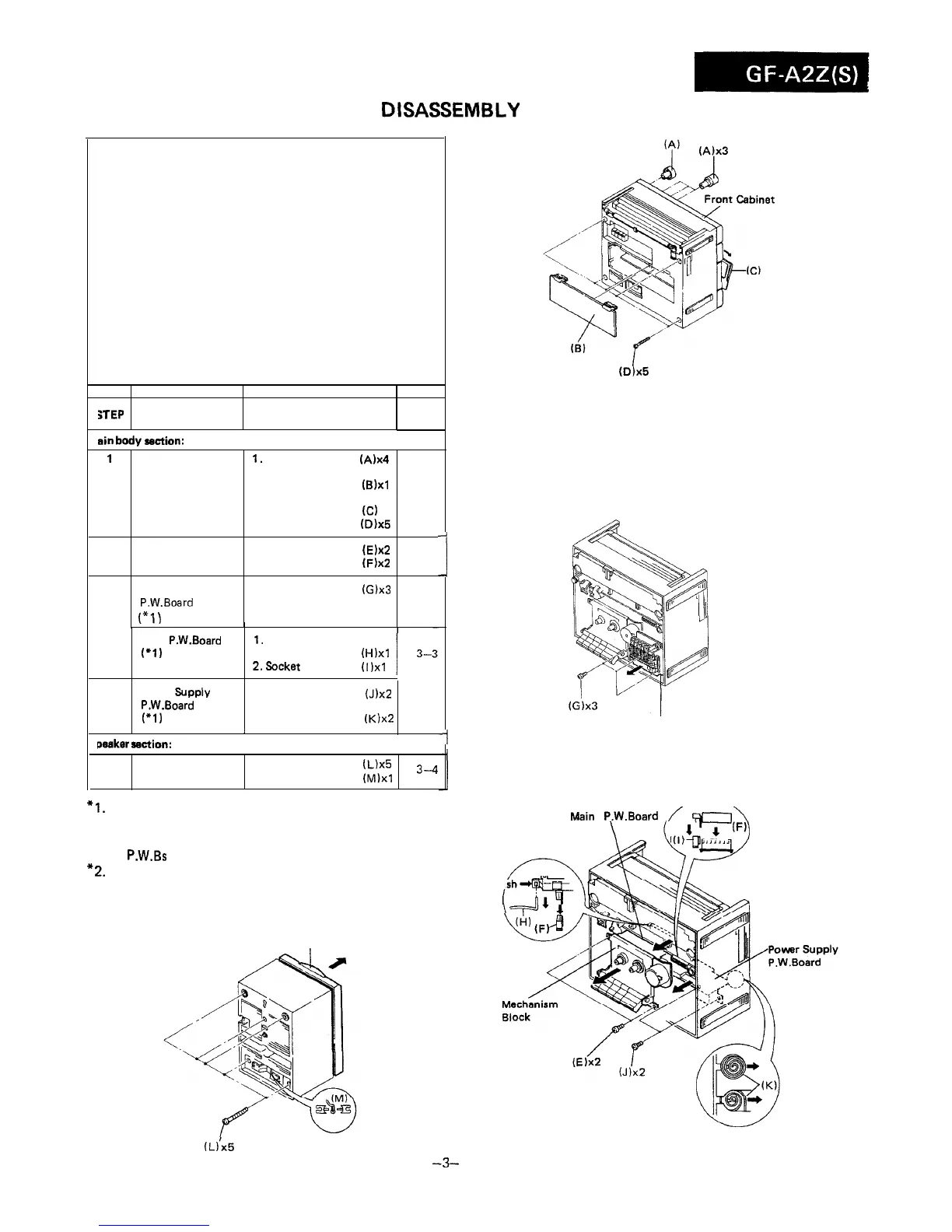
DISASSEMBLY
Caution on Disassembly
Follow the below-mentioned notes when disassembling the
unit and reassembling it, to keep its safety and excellent
performance:
1. Take cassette tape out of the unit.
2. Be sure to remove the power supply plug from the wall
outlet before starting to disassemble the unit and remove
the batteries from the unit.
3. Take off nylon bands or wire holders where they need be
removed when disassembling the unit. After servicing
the unit, be sure to rearrange the leads where they were
before disassembling.
4. Take sufficient care on static electricity of integrated
circuits and other circuits when servicing.
iTEP
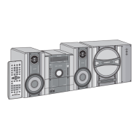
REMOVAL
PROCEDURE
FIGURE
1
sin
body
section:
1
Front cabinet
1.
Knob . . . . . . .
(A)x4
2. Battery compartment
lid
. . . . . . . , .
03)x1
3. Open the cassette
holder . . . . . . . (C)
4. Screw . . . . . . .
(D)x5
3-l
2 Mechanism block 1. Screw . . . . . . .
(E)x2
2. Socket . . . . . .
(F)x2
3-3
Graphic Equalizer 1. Screw (G)x3
P.W.Board
3-2
(“1)
I
3
Main P.W.Board
1.
Record interlocking
(‘1)
lever. . . . . . .
(H)xl
(‘2)
2.Socket
. . . . . .
(1)x1
4
Power Bupply
1. Screw . . . . . . . (J)x~
P.W.Board 2. Battery terminal
(‘1)
spring . . . . . . .
(K)x2
I
,
paaker
section:
Front Cabinet
1. Screw , . . . . . .
(L)x5
2. Speaker Cord . .
(~)xl
3--4
-I
*I.
Each P.W.B. should be removed until the parts to be
exchanged can be removed when servicing. If the parts to
be exchanged are in the exchangeable condition, the rest
of
P.W.Bs
need not to be removed.
*2.
When taking the main P.W.B. out the unit, the P.W.B.
cannot be removed unless the every external speaker
terminal knobs located at the rear side are let down.
Front Cabinet
I
(D)x5
Figure 3-l
Graphic Equalizer P.W. Board
Figure 3-2
Vain
P.W.Board
/
F‘c7\
.
.
.
\
Pu
!
(L)‘x5
Figure 3-4
-3-
Figure 3-3