FOR
A
COMPLETE DESCRIPTION OF THE OPERATION OF THIS UNIT,
PLEASE REFER TO THE OPERATION MANUAL.
1.
Built-in Microphone
2. Band Selector Switch
3.
FM
Stereo Indicator
4. Function Selector Switch
5.
Volume Control
6.
Balance Control
7. Fine Tuning Control
8.
Power Indicator
9. Sound Level Meter
10.
Tuning Control
11.
Headphones Jack
12.
Cassette Compartment
13.
Record Button
14.
Rewind Button
15.
Play Button
16.
Fast-Forward Button
17.
Stop/Eject Button
18. Graphic Equalizer Controls
19. Speaker Release Knob
20. External Speaker Terminals
21.
External Microphone Jack
22. FM/SW Telescopic Rod Antenna
23.
Battery Compartment
24. Speaker Cord Holder
25. AC Power Supply Socket
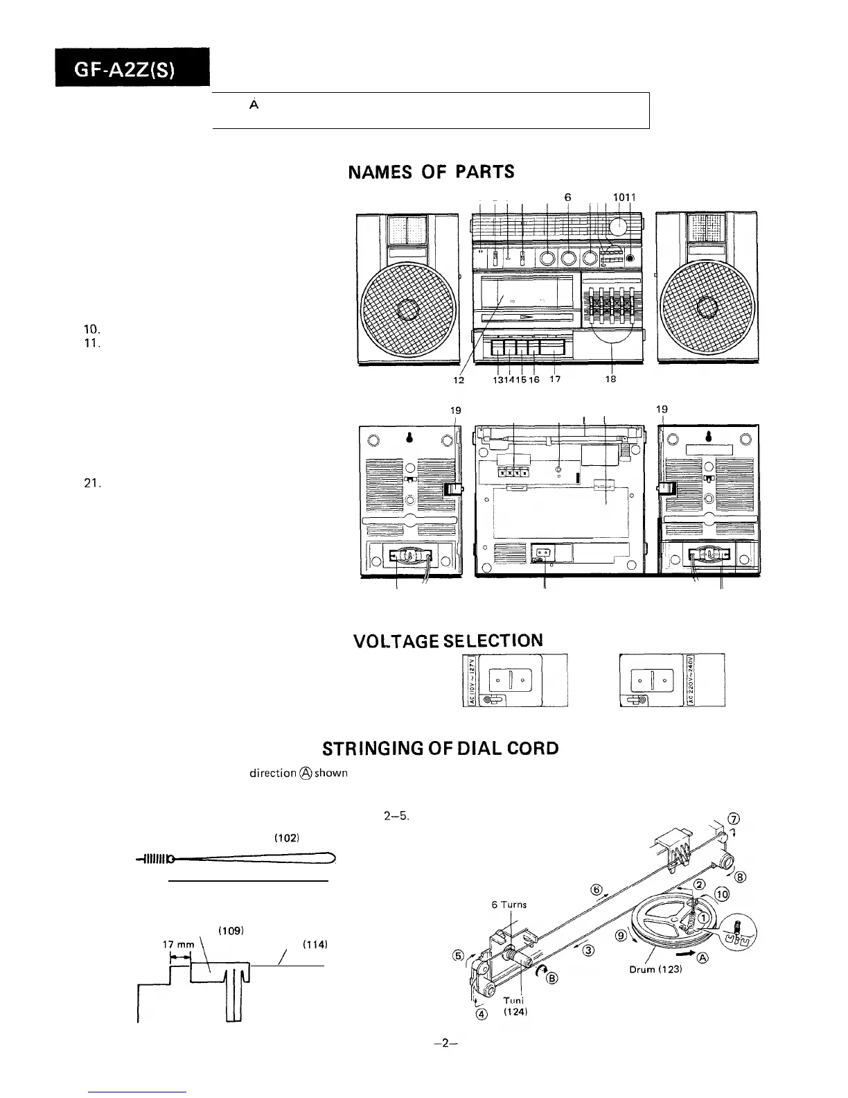
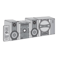
NAMES OF PARTS
1234 5 6
789 1011
Figure 2-l
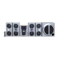
20
21
22 23
I
I I
I
24
25
Figure 2-2
24
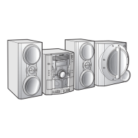
VOLTAGE
SELECTION
Before operating the unit on mains,
check
the preset voltage.
If the voltage is different from your local voltage,
adjust the
voltage as follows: Slide the AC power supply socket cover by
slightly loosing the screw to the visible indication of the side
mi
m’:1II
of your local voltage.
Figure 2-3
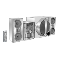
STRINGING
OF
DIAL
CORD
1. Turn the drum fully in the
direction@shown
in Fig. 2-4
and stretch its cord over the parts in the numerical order.
2. Then turn the tuning control shaft fully in the direction@
shown in Fig. 2-4 and fix its pointer as shown in Fig.
2-5.
Spring
with Dial Cord
(102)
451 mm
Pointer
(109)
17 mm
Frame
(114)
f9
/
Figure 2-5
ing Control Shaft
Figure 2-4