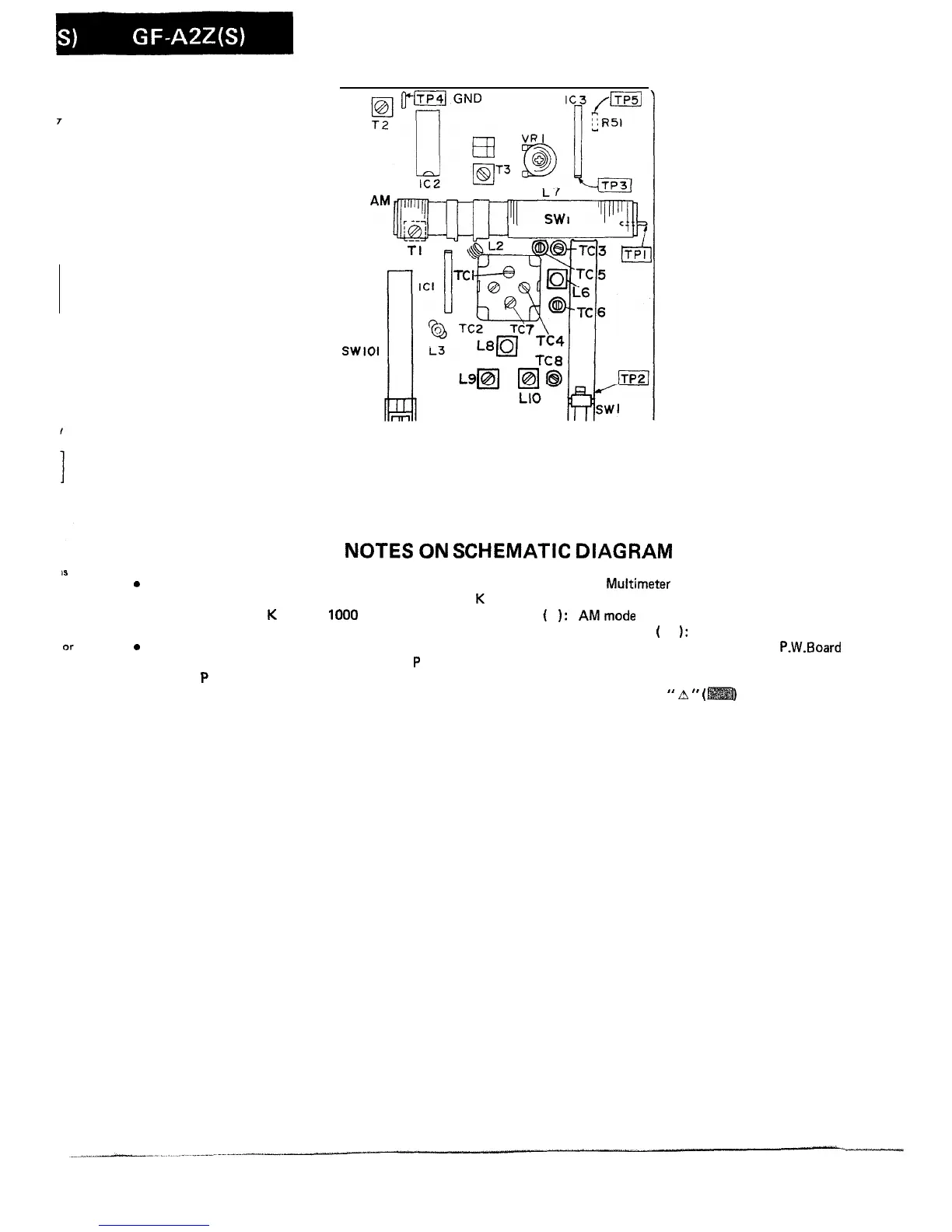
Figure 8-l ADJUSTMENT POINT
NOTES
ON
SCHEMATIC
DIAGRAM
0
Resistor:
To differentiate the units of resistors, such symbol as
K
is
used: the symbol
K
means
1000
ohm and the resistor
without any symbol is ohm-type resistor.
0
Capacitor:
To indicate the unit of capacitor, a symbol
P
is used: this
symbol
P
means micro-micro-farad and the unit of the
capacitor without such a symbol is microfarad. As to elec-
trolytic capacitor, the expression “capacitance/withstand
voltage” is used.
l
The indicated voltage in each section is the one measured
by Digital
Multimeter
between such a section and the
chassis with no signal given.
(
1:
AMmode
Marking except for
(
1:
FM mode
l
Schematic diagram and Wiring Side of
P.W.Board
for this
model are subject to change for improvement without prior
notice.
. Parts marked with
”
A
”
(
1
are important for main-
taining the safety of the set. Be sure to replace these parts
with specified ones for maintaining the safety and per-
formance of the set.
-8-