Do you have a question about the Sharp GX-CD130C and is the answer not in the manual?
| Brand | Sharp |
|---|---|
| Model | GX-CD130C |
| Category | Stereo System |
| Language | English |
Safety checks to prevent fire and shock hazards.
Technical specifications of the audio product.
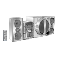
Identification of parts on the main audio unit.
Identification of parts on the remote control.
Important precautions before disassembling the unit.
Step-by-step guide for disassembling the unit.
Procedures for removing tape mechanism components.
Detailed steps for removing tape heads.
Detailed steps for removing tape playback head.
Steps for removing pinch rollers.
Steps for removing tape mechanism belts.
Steps for removing tape mechanism motors.
Steps to remove the CD pickup mechanism.
Removing tuner PWB and adjusting the dial wheel.
Checks and adjustments for the tape mechanism.
Adjustment procedures for the tuner section.
Adjustment points for FM Intermediate Frequency/Radio Frequency.
Adjustment points for AM Intermediate Frequency/Radio Frequency.
Adjustment of the Voltage Controlled Oscillator frequency.
Procedures to enter and use the test mode.
Explanation of the LCD display modes.
Troubleshooting steps for when the CD function fails.
Troubleshooting when CD keys operate but CD does not.
Troubleshooting playback requiring a loaded disc.
Detailed checks for the CD tracking system.
Troubleshooting steps for the CD spin system.
Troubleshooting steps for the VCO-PLL system.
Diagnosing no sound with normal HF waveform.
Explanation of resistor symbols and designations.
Explanation of capacitor symbols and designations.
Explanation of symbols used in schematic diagrams.
Identification of safety-critical parts.
Block diagram of the microcomputer and pickup unit.
Block diagram of the laser driver and driver IC.
Block diagram of the servo amplifier and control IC.
Block diagram of the driver IC.
Block diagram of FM front-end and IF MPX ICs.
Block diagram of the playback/record amplifier.
Block diagram of the power amplifier IC.
Diagram of power transformer and tape mechanism.
Schematic for the laser driver.
Schematic for the servo amplifier IC.
Schematic for the servo/signal control IC.
Schematic for the servo/signal control IC.
Schematic for the driver IC.
Schematics for the motors.
Wiring diagram for the switch PWB.
Wiring diagram for the display PWB.
Wiring diagram for the CD motor PWB.
Wiring diagram for the CD servo PWB.
Schematic for the FM front-end IC.
Schematic for the FM/AM IF MPX IC.
Schematic for the playback/record amplifier.
Schematic for the power amplifier IC.
Schematic for the power transformer.
Schematic block for the tape mechanism.
Wiring diagram for the tuner PWB.
Wiring diagram for the power PWB.
Wiring diagram for the terminal PWB.
Wiring diagram for the main PWB.
Wiring diagram for the deck PWB.
Schematic diagram for the display PWB.
Schematic diagram for the switch PWB.
Function table for the system control microcomputer.
Instructions for ordering replacement parts.
General reference information for parts identification.
Information on identifying capacitors.
Information on identifying resistors.
List of ICs, transistors, and diodes with part numbers.
List of passive components like filters, transformers, and coils.
List of resistors with part codes.
List of other circuitry components with part codes.
List of mechanism parts with part codes.
List of CD mechanism parts with part codes.
List of cabinet parts with part codes.
List of speaker box parts with part codes.
List of accessories and PWB assemblies.
Exploded view of the CD mechanism.
Exploded view of the tape mechanism.
Exploded views of cabinet components and sub-assemblies.
Exploded view of the speaker box.
Recommended switch and knob settings for packing.