GX-CD30/30C/130/130C
– 13 –
NOTES ON SCHEMATIC DIAGRAM
1. Tuner
( ): AM mode
Marking except for ( ): FM mode
2. CD
( ): Play mode
Marking except for ( ): Stop state
3. Deck section
( ): Record mode
Marking except for ( ): Playback mode
Display / Control section:
( ): Active state
Marking except for ( ): CD Function mode at stop state
• Schematic diagram and Wiring Side of P.W.Board for this
model are subject to change for improvement without prior
notice.
• Parts marked with “ î ” ( ) are important for
maintaining the safety of the set. Be sure to replace these
parts with specified ones for maintaining the safety and
performance of the set.
• Resistor:
To differentiate the units of resistors, the symbol as K and M
are used: the symbol K means 1000 ohm and the symbol M
means 1000 kohm and the resistor without any symbol is an
ohm resistor. The resistor designated "Fusible" is a fuse type
resistor
• Capacitor:
To indicate the unit of capacitor, a symbol P is used: this
symbol P means micro-micro-farad and the unit of the capacitor
without such a symbol is microfarad. As to electrolytic capacitor,
the expression “capacitance/withstand voltage” is used.
(CH), (TH), (RH), (UJ): Temperature compensation
(ML): Mylar type
(P.P.): Polypropylene type
• The indicated voltage in each section is the one measured by
Digital Multimeter between such a section and the chassis
with no signal given.
SW201 RECODE/PLAYBACK OFF
SW351 BEAT CANCEL A
SW500 X-BASS [130/130C ONLY] OFF
SW501 POWER/FUNCTION OFF
SW605 TAPE 1 MAIN OFF
SW606 TAPE 2 MAIN OFF
SW607 TAPE1/2 SELECTOR OFF
REF. NO DESCRIPTION POSITION POSITIONREF. NO DESCRIPTION
SW702 PICKUP IN OFF
SW761 CD LID OPEN/CLOSE OFF
SW771 CD-PLAY/REPEAT OFF
SW772 CD-STOP OFF
SW773 CD-UP/CUE OFF
SW774 CD-DOWN/REVIEW OFF
SW775 CD-PAUSE OFF
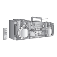
ECB
(S)(G)(D)
(1) (2) (3)
FRONT
VIEW
2SC2001 K
2SD468 C
KRA102 M
KRC102 M
KTA1266 GR
KTC3199 GR
Figure 13 TYPES OF TRANSISTOR
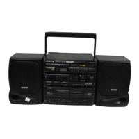
BCE
FRONT
VIEW
2SD2394 F