Is pin 17 of CNPQ51
i
Yes
No
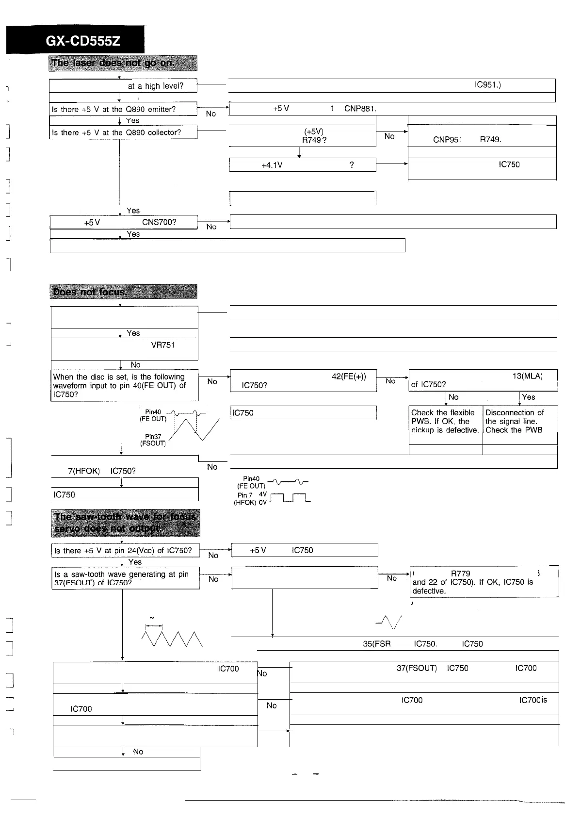
Check the LCD PWB of CD. (Check the LD ON terminal of pin 9 of
IC951.)
Check the
+5
V
line of pin
1
of
CNP881.
No
Is there a high level
(+5V)
between pin
17 of CNP951 and
R749
?
No
c
Check the PWB pattern between pin
17 of
CNP951
and
R749.
1
Yes
Is there
+4.1V
at the Q890 base
?
Yes
Q890 is defective
No
+
Check between pin 1 of
IC750
and
Q890 base.
I
Is there
+5
V
at pin 5 of
CNS700?
The PWB pattern between Q890 and pin 5 of CNS700 is damaged.
Check the CNS700 and Flexible PWB. If they are normal, the pickup is defective.
1
1
1
1
When the disc is removed, is the
pickup moving up and down?
No
Check the item of “The saw-tooth wave for focus servo does not output”.
Is the focus gain adjusting
VR751
set
to the minimum position?
Yes
Readjust the focus gain.
Is a waveform output at pin
42(FE(+))
of
IC750?
Is a waveform output at pin
13(MiA)
Yes
Yes
IC750
is defective.
1
Pi”37
/
V
(FSOUT)
pattern and parts.
c
Is the waveform shown at right input at
’
No
The pickup is defective.
pin
7(HFOK)
of
IC750?
1
Yes
(FpE’%)
-+---%-
IC750
is defective.
The
+5
V
line of
IC750
is defective.
Does the saw-tooth wave look like the
following waveform?
Check the
R779
and C767 (pins 23
Yes
Yes. (The saw-tooth wave oscillates to
1
-
2sec
m
the positive side once.)
4
Check the peripheral circuits of pin 35(FSR IN) of
IC750.
If OK,
IC750
is defective.
Is the saw-tooth wave being input to pin 8 of
IC700
(same waveform as shown above)?
1
Yes
No
l
The signal line between pin
37(FSOUT)
of
IC750
and pin 8 of
IC700
is
connected improperly.
Is the saw-tooth wave generating between pins 3 and
6 of
IC700
(same waveform as shown above)?
1
Yes
No
l
Check the peripheral parts of
IC700
and the power line. If OK,
IC700
iS
defective.
Is the saw-tooth wave generating between pins 2 and
3 of CNS700 (same waveform as shown above)?
i
No
+
The CNS700 and flexible PWB are connected improperly or the pickup is
Yes
defective.
The PWB pattern is damaged.
-
34
-