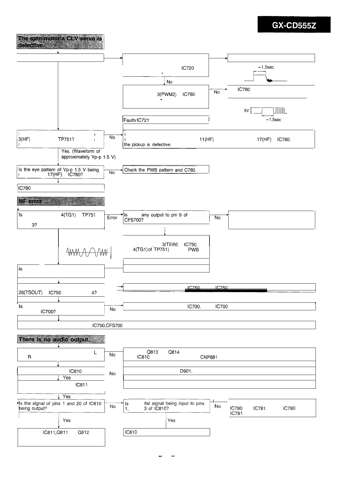
is the spin motor running?
I
No
+
When test mode 2 is switched to test
Yes
c
Faulty spin motor or disconnection
mode 3, does voltage generate
Yes. (Runs at extremely
high speed)
between pins 11 and lb of
IC720
for
approximately 0.3
-
1.5 seconds?
When test mode 2 is switched to test
-
mode 3, is pin
3(PWM2)
of
IC780
at a
high level for 0.3
-
1.5 seconds and
then does a pulse generate?
Yes
/
Faultv
IC721
or disconnection
/
0.3
-
1.5sec
J=lb---
x-+
The
IC780
or microcomputer section is
defective.
Nx-JmlL
0.3
-
1.5sec
Is an eye pattern being output to pin
3(HF)
of test point TP751? (Even an
unclear waveform is allowable.)
Check if the objective lens of the pickup is dirty. If so, clean it.
Check the connection between pin
ll(HF)
of CNS700 and pin
17(HF)
of
IC780.
If OK,
output to pin
17(HF)
of
IC780?
1
Yes
/
IC780
is defective.
i
Is
the output of pin
4(TGl)
of
TP751
+
Is
there
any-
*
Check the connection between the
(tracking error signal) normal in test
Error
CFS700?
I
No
CNP700 and flexible PWB. If OK, the
mode
3?
I
pickup is defective.
1
Yes
Normal
Check the connection between pin 9 of
CNS700 and pin
3(TEIN)
of
IC750
(or
pin
4(TGl)
of’TP751) and the
PWB‘
*&4+w
(
pattern.
c
Is
the tracking gain adjusting VR750
set to the minimum position?
. .
Yes
l
Readjust the tracking gain.
1
NO
Is there any tracking output to pin
-*
Check the peripheral parts of
IC750.
If OK,
IC750
is defective.
28(TSOUT)
of
IC750
in test mode
4?
No
I
1
Yes
I
is
there any output between pins 11
and 14 of
IC700’7
1
No
Check the peripheral parts of
IC700.
If OK,
IC700
is defective.
1
Yes
Check the connection between the
IC7OO,CFS700
and flexible PWB If OK, the pickup is defective.
There is no audio output from both
L
and
R
channels.
No
. Check the
Q813
and
Q814
(for muting). Check the connection between the pins 1 and
20 of
IC810
and the pin 6 and 7 of
CNP881
1
Yes
1
Is the supply voltage of
IC810
normal?
No
Check the power line and
DQOl.
Are the supply voltages of
IC811
normal?
No
Check the power line and the power circuit of the main unit.
Is the signal of pins 1 and 20 of
IC810
Is the digital signal being input to pins
’
No
F-lrcDil,
2 and
““““I”:.,?
1
Check the connection between the
IC780
and
IC781.
If OK,
IC780
or
IC781
is defective.
.
Check the
IC811
,Q811
and
Q812
along the signal flow and then the
connection between them.
IC810
is defective.
-
35
-