HT-DV40H
8 – 32
IC5 : FLASH ROM, 48 BIT ( EN29LV800B ) ( 2/2 )
*Note: Refer Parts Guide page 1 under item [1] INTEGRATED CIRCUITS
PIN DESCRIPTION
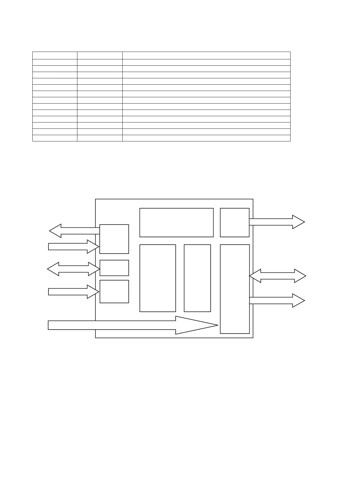
IC6 VHISPHE6500P- : HDMI TRANSMITTER, 128 Pin ( SPHE6500P ) ( 1/3 )
BLOCK DIAGRAM
Pin No. Pin Name Function
1~9, 16~25 A0-A19 Addresses
29~36, 38~44 DQ0-DQ14 15 Data Inputs/Outputs
45 DQ15/A-1 DQ15 (data input/output, word mode), A-1 (LSB address input, byte mode)
26 CE# Chip Enable
28 OE# Output Enable
12 RESET# Hardware Reset Pin
15* RY/BY# Ready/Busy Output
11 WE# Write Enable
37 Vcc Supply Voltage (2.7-3.6V)
27, 46 Vss Ground
10*, 13* NC Not Connected to anything
47 BYTE# Byte/Word Mode
14 WPB Write protect function
In this unit, the terminal with asterisk mark (*) is (open) terminal which is not connected to the outside.
Display Clock
PLL
12C
S & IP
VII
VO
HDMI
DACTV Encoder
Crystal Clock
Video Input
Audio Input (SPDIF/12S)
Video Analog Output
TMDS/EXT_SWING
DDC 12C/HPD
12 C