HT-M700H
3 – 1
HT-M700H
Service Manual
CHAPTER 3. MECHANISM BLOCKS
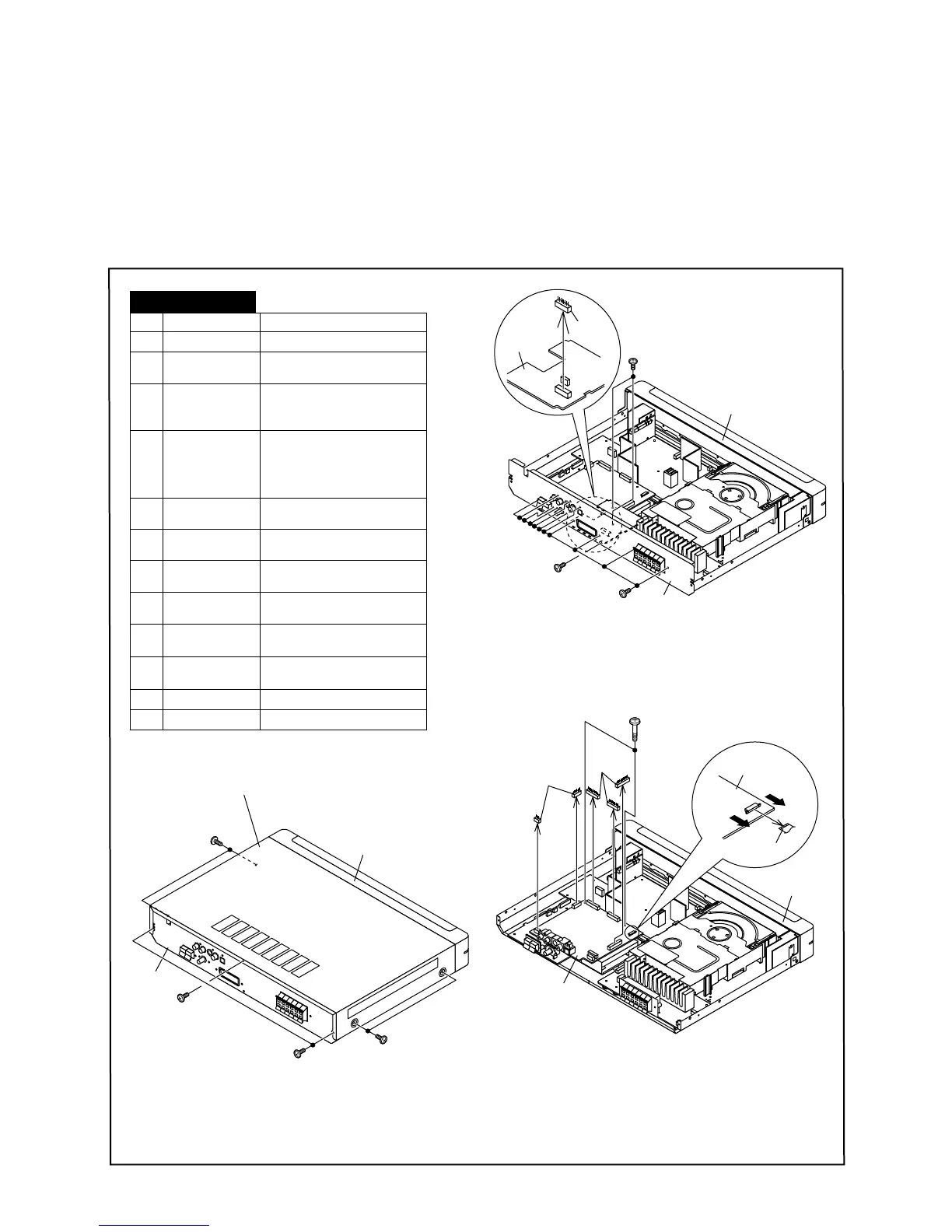
[1] Caution on disassembly
Caution on disassembly
Follow the below-mentioned notes disassembling the unit and reassembling it, to keep it safe and ensure excellent performance:
1. Take DVD and compact disc out of the unit.
2. Be sure to remove the power supply plug from the wall outlet before starting to disassemble the unit.
3. Take off nylon bands or wire holders where they need to be removed when disassembling thr unit. After servicing the unit, be sure to rearrange the
leads where they were before disassembling.
1 Top Cabinet 1. Screw ....................... (A1) x7
1. Screw ...................... (C1) x2
2 Rear Panel/
SCART PWB
1. Screw ..................... (B1) x14
2. Socket ...................... (B2) x1
3 Decode PWB
Tuner PWB
2. Socket ..................... (C2) x5
3. Flat Cable ................ (C3) x1
4
1. Screw ...................... (D1) x5
2. Screw ...................... (D2) x3
3. Shield, B
.....................
2. Socket .....................
(D3) x1
4. Shield, A ..................
..................
(D4) x1
5. Socket (D5) x1
......................
5 Power PWB 1. Screw ...................... (E1) x5
6 Motor Driver
PWB
1. Screw ...................... (F1) x2
(F2) x3
2. Socket ..................... (E2) x4
7 DVD Mechanism
Ass'y
1. Screw ...................... (G1) x4
2. Screw ...................... (H2) x2
8 Speaker Terminal
PWB
1. Screw (H1) x5
......................
2. Hook ........................ (J2) x2
9 Front Panel 1. Screw (J1) x5
....................
2. Socket ..................... (K2) x2
10 Display PWB 1. Screw (K1) x10
......................
11
Headphones PWB
1. Screw (L1) x2
......................
12
Remote Control PWB
1. Screw (M1) x2
STEP
REMOVAL PROCEDURE
HT-M700H
(A1)x1
φ3x6mm
(A1)x2
φ3x6mm
(A1)x2
φ3x6mm
(A1)x2
φ3x6mm
Top Cabinet
Front Panel
Rear Panel
(C1)x2
φ3x40mm
(C2)x2
(C3)x1
(C2)x3
Pull
Pull
Decode PWB
Decode PWB
Front Panel
Front Panel
(B1)x1
φ3x6mm
(B1)x11
φ3x8mm
(B1)x2
φ3x10mm
(B2)x1
Rear Panel
SCART
PWB