HT-M700H
5 – 1
HT-M700H
Service Manual
CHAPTER 5. CIRCUIT DESCRIPTION
[1] Notes on schematic diagram
•Resistor:
To differentiate the units of resistors, such symbol as K and M are
used: the symbol K means 1000 ohm and the symbol M means
1000 kohm and the resistor without any symbol is ohm-type resis-
tor. Besides, the one with "Fusible" is a fuse type.
• Capacitor:
To indicate the unit of capacitor, a symbol P is used: this symbol P
means pico-farad and the unit of the capacitor without such a sym-
bol is microfarad. As to electrolytic capacitor, the expression
"capacitance/withstand voltage" is used.
(CH), (TH), (RH), (UJ): Temperature compensation
(ML): Mylar type
(P.P.): Polypropylene type
• Schematic diagram and Wiring Side of P.W.Board for this model
are subject to change for improvement without prior notice.
• The indicated voltage in each section is the one measured by Digi-
tal Multimeter between such a section and the chassis with no sig-
nal given.
1. In the tuner section,
indicates AM
indicates FM stereo
2. In the CD section, the CD is stopped.
• Parts marked with " " ( ) are important for
maintaining the safety of the set. Be sure to replace these parts
with specified ones for maintaining the safety and performance of
the set.
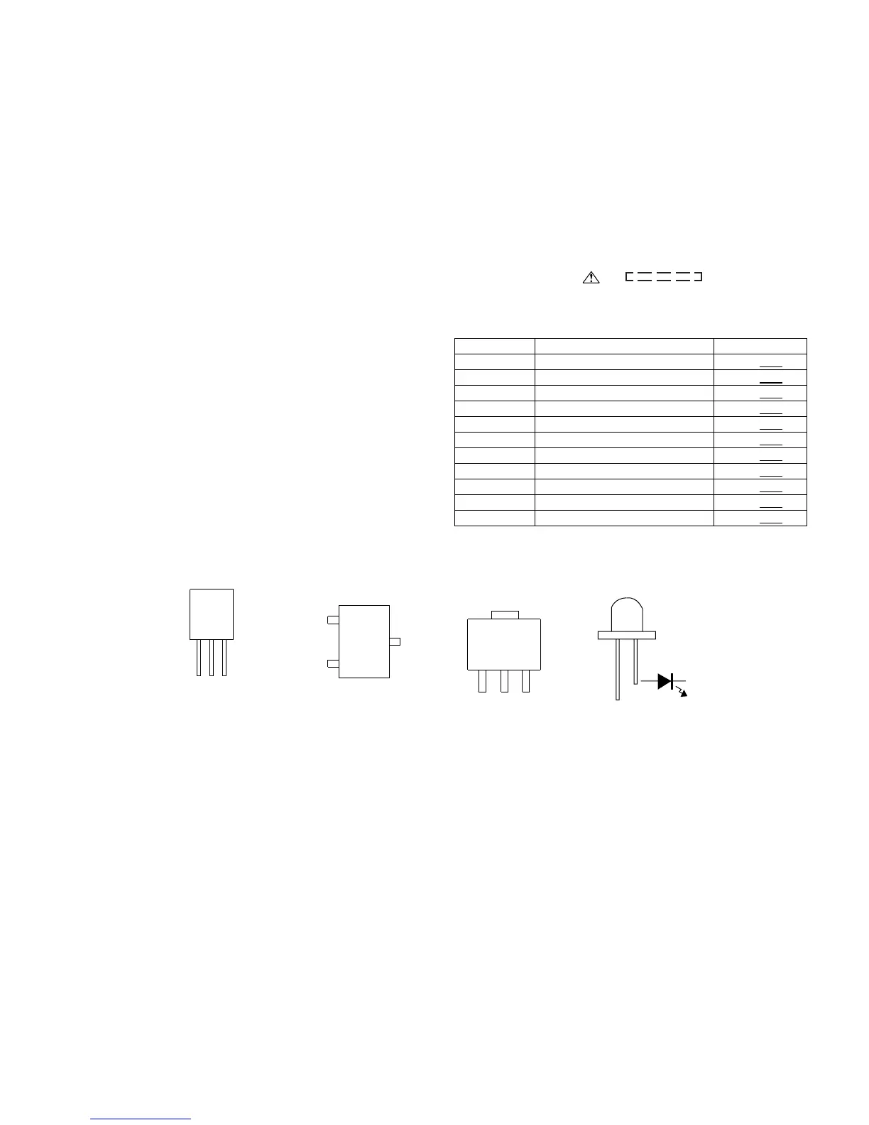
[2] Types of transistor and LED
REF NO. DESCRIPTION POSITION
SW501 OPEN/CLOSE ON-OFF
SW601 DOOR ON-OFF
SW701 PLAY ON-OFF
SW702 STOP ON-OFF
SW703 DISC TRAY OPEN/CLOSE ON-OFF
SW705 TUNER (BAND) ON-OFF
SW706 FUNCTION ON-OFF
SW707 NEXT ON-OFF
SW708 PREV ON-OFF
SW709 JOG VOLUME ON-OFF
SW801 ON/STAND-BY ON-OFF
2N2904
2N2907
2N3904
2N3906
2N8050
2SC3326
2SB1132 Q LPBB73VQ
B
(3)
E
(1)
C
(2)
BCE
TOP
VIEW
TOP
VIEW
2SA1015
2SA562
2SC380 O
2SC1815 GW
C2001 SG
CMT20N15
KRA107 M
KRC104 M
KRC107 M
KTA1266 GR
KTA1271 Y
KTC3199 GR
KTC3203 y
RHC1815 GR
RF640B
VIEW
FRONT
ECB
(S)(G)(D)
(1)(2)(3)
FRONT
VIEW