HT-X1H
5 – 1
AudioHT-X1HService ManualHT-X1HMarketE
CHAPTER 5. CIRCUIT DESCRIPTION
[1] Notes on schematic diagram
•Resistor:
To differentiate the units of resistors, such symbol as K and M are
used: the symbol K means 1000 ohm and the symbol M means
1000 kohm and the resistor without any symbol is ohm-type resis-
tor. Besides, the one with “Fusible” is a fuse type.
• Capacitor:
To indicate the unit of capacitor, a symbol P is used: this symbol P
means pico-farad and the unit of the capacitor without such a sym-
bol is microfarad. As to electrolytic capacitor, the expression
“capacitance/withstand voltage” is used.
(CH), (TH), (RH), (UJ): Temperature compensation
(ML): Mylar type
(P.P.): Polypropylene type
• Schematic diagram and Wiring Side of P.W.Board for this model are
subject to change for improvement without prior notice.
• The indicated voltage in each section is the one measured by Digi-
tal Multimeter between such a section and the chassis with no sig-
nal given.
1. In the tuner section,
indicates AM
indicates FM stereo
2. In the CD section, the CD is stopped.
• Parts marked with “ “ ( ) are important for main-
taining the safety of the set. Be sure to replace these parts with
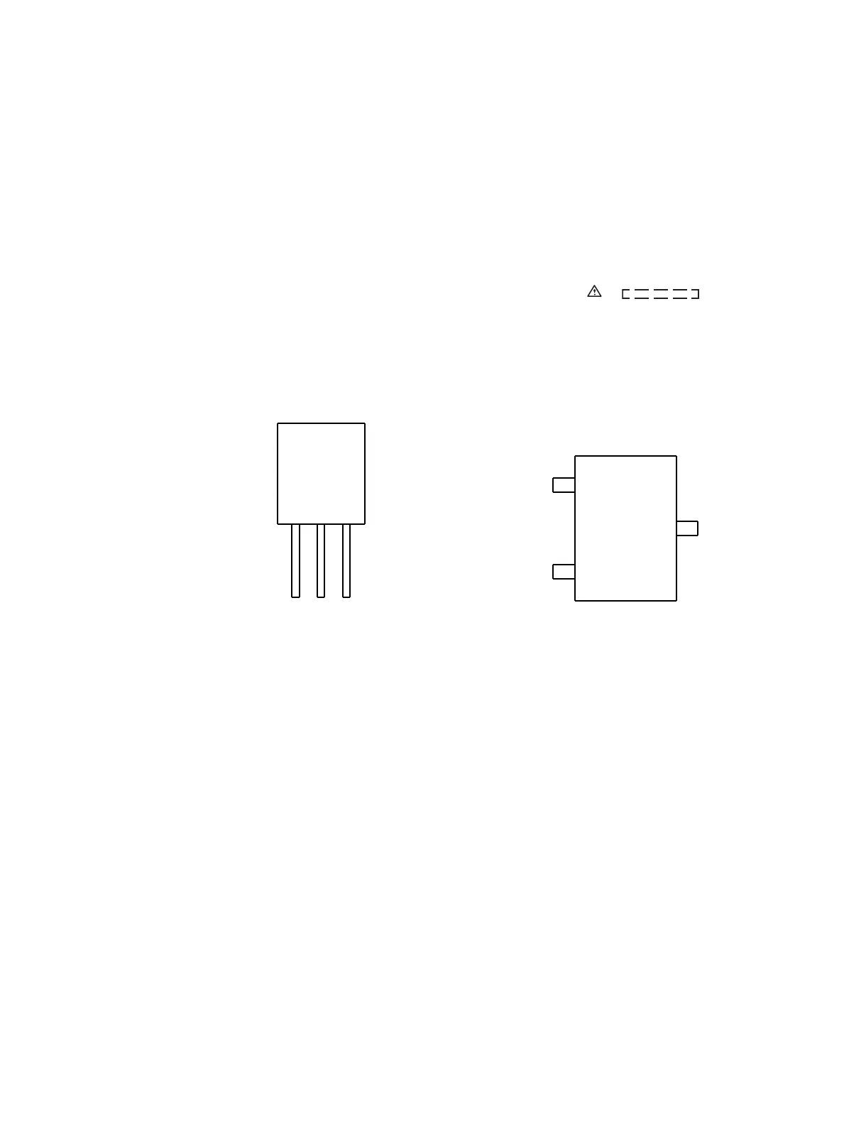
[2] Types of transistor
2SD601 AR
B
(3)
E
(1)
C
(2)
TOP
VIEW
2HC1815 GR
2SC535 C
2SC380 O
KRC104 M
KTA1266 GR
KTA1271 Y
KRA107 M
VIEW
FRONT
ECB
(S)(G)(D)
(1)(2)(3)
KRC107 M
KTC3199 GR
KTC3200 GR
KTC3203 Y
2SB562 C