11
LC-20S1M
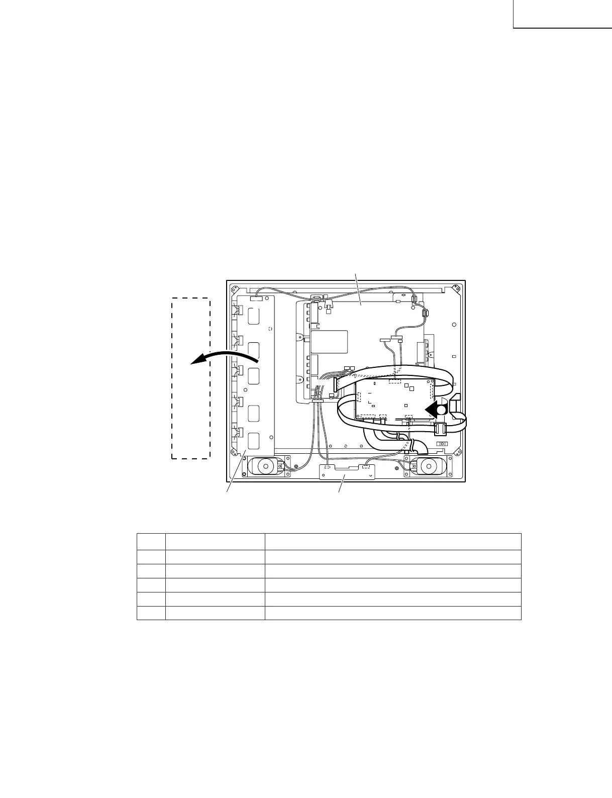
Precautions at the time of the side B(back) service of Main unit.
1. Remove the FFC for connection between Main unit (SC2001) and Sub unit(SC3401), and connect the extended
cable (QCNW-A556WJZZ) for service.
2. Remove only SC1204 of the FFC for connection between Main unit (SC1204) and LCD panel unit, and connect
the extended cable (QCNW-A553WJZZ) for service.
3. Remove the FFC for connection between Main unit (SC1203) and LCD panel unit, and connect the extended
cable (QCNW-A556WJZZ) for service.
4. Remove the FFC for connection between Main unit (SC1202) and LCD panel unit, and connect the extended
cable (QCNW-A555WJZZ) for service.
5. Remove the main unit fixing screws (3 pcs.), a substrate is reversed.
Precautions at the time of the side B(back) service of Inverter unit.
6. Remove only P6706 of the cable for connection between Inverter unit (P6706) and Sub unit(P3604), and connect
the extended cable (QCNW-B749WJQZ) for service.
7. Remove the Inverter unit fixing screws (3 pcs.), a substrate is reversed.
Step Part No. Description
1 QCNW-A556WJZZ Extension Cable 50-pin Main (SC2001)-Sub (SC3401)
2 QCNW-A553WJZZ Extension Cable 30-pin Main (SC1204)-LCD Panel
3 QCNW-A556WJZZ Extension Cable 50-pin Main (SC1203)-LCD Panel
4 QCNW-A555WJZZ Extension Cable 20-pin Main (SC1202)-LCD Panel
6 QCNW-B749WJQZ Extension Cable 10-pin Inverter (P6706)-Sub(P3604)
SC1204
P3701
P3604
P701
P2001
P4001
SC1202SC1203
SC3401
P6706
SC2001
R/C, LED PWB
4
1
5
2
3
Inverter PWB
6
7
Main PWB
(Side B)
Inverter
PWB
(Side B)
Sub PWB