8
LC-20S1M
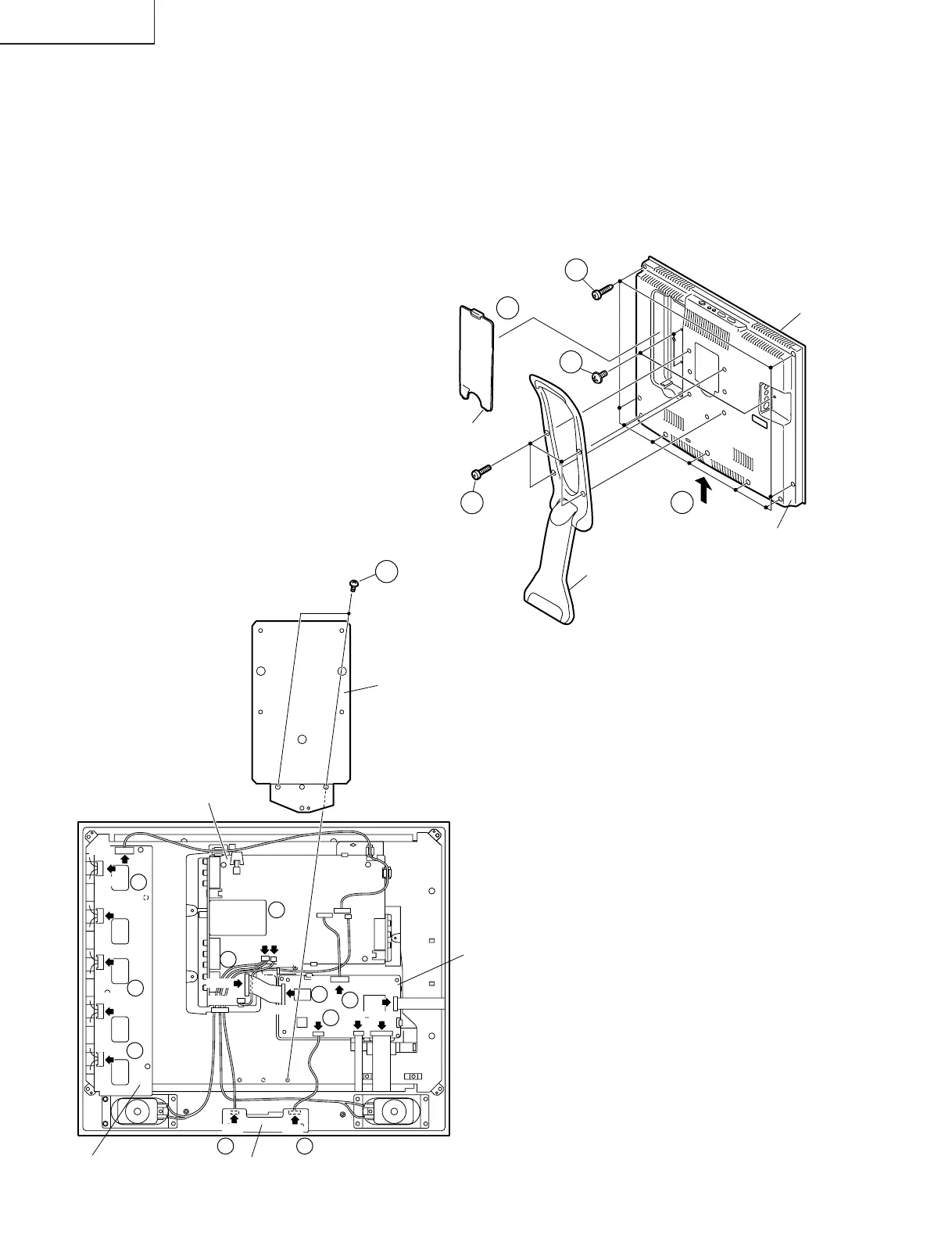
REMOVING OF MAJOR PARTS
1. Remove the stand fixing screws (4 pcs.).
2. Remove the terminal cover.
3. Remove the terminal section fixing screws (3 pcs.).
4. Remove the cabinet B fixing screws (9 pcs.).
5. Remove the cabinet B after opening from the direction of an arrow.
6. Remove the reinforcement angle fixing screws (2 pcs.).
7. Detach the connector from each PWB.
Cabinet A
Cabinet B
Stand
Terminal Cover
4
3
2
5
1
P6706
SC1204
P3701
P3603
P701
P3303
P3302
P2001
P4001
P4003
SC1202
SC1203
SC2001
P6706
P6701
P6702
P6703
P6704
P6700
P5602
SC3401
P3604
7
7
7
7 7
7
7
7
7
7
6
Inverter
PWB
R/C, LED
PWB
Main PWB
Sub PWB
Reinforcement Angle