EasyManua.ls Logo

Sharp LC-24LE150M

Sharp LC-24LE150M
54 pages
To Next Page IconTo Next Page
Loading...
SERVICE MANUAL
No.S53M2024LE150M
CONTENTS
Parts marked with " " are important for maintaining the safety of the set. Be sure to replace these parts with specified ones for maintaining the
safety and performance of the set.
This document has been published to be used for
after sales service only.
The contents are subject to change without notice.
SAFETY PRECAUTION
IMPORTANT SERVICE SAFETY
PRECAUTION................................................i
PRECAUTION FOR USING LEAD-FREE
SOLDER.........................................................ii
CHAPTER 1. OUTLINE
[1] OUTLINE...........................................1-1
CHAPTER 2. SPECIFICATIONS
[1] SPECIFICATION.................................2-1
CHAPTER 3.OPERATION MANUAL
[1] OPERATION MANUAL........................3-1
CHAPTER 4. DIMENSIONS
[1] DIMENSIONS......................................4-1
CHAPTER 5. REMOVING OF MAJOR PARTS
[1] REMOVING OF MAJOR PARTS...........5-1
CHAPTER 6. ADJUSTMENT
[1] ADJUSTMENT....................................6-1
CHAPTER 7. TROUBLESHOOTING TABLE
[1] TROUBLESHOOTING TABLE .........................7-1
CHAPTER 8. OVERALL WIRING/BLOCK DIAGRAM
[1] SYSTEM BLOCK DIAGRAM............................8-1
CHAPTER 9. PRINTED WIRING BOARD ASSEM-
BLIES
[1] Main Unit .............................................9-1
[2] LED RC Unit ........................................9-5
[3] POWER Unit........................................9-7
CHAPTER 10. SCHEMATIC DIAGRAM
[1] DESCRIPTION OF SCHEMATIC
DIAGRAM ...........................................10-1
[2] MAIN Unit ...........................................10-2
[3] LED RC Unit .......................................10-4
[4] POWER Unit ......................................10-6
Parts Guide
TopPage
In the interests of user-safety (Required by safety regulations in some countries) the set should be restored to its orig-
inal condition and only parts identical to those specified should be used.
MODEL : LC-24LE150M
LED BACKLIGHT TV
Question and Answer IconNeed help?

Do you have a question about the Sharp LC-24LE150M and is the answer not in the manual?

Sharp LC-24LE150M Specifications

General IconGeneral
Screen Size24 inches
Resolution1366 x 768
Display TypeLED
HDMI Ports2
USB Ports1
Resolution TypeHD
Backlight TypeLED

Summary

SAFETY PRECAUTIONS

Important Service Safety Precautions

Service work should be performed by qualified technicians familiar with safety checks and guidelines.

Service Warnings and Hazards

Key warnings for service work, including circuit modification and shock hazards.

Safety Notices and Part Replacements

Notes on special safety characteristics of parts and using specified replacement parts.

LEAD-FREE SOLDER PRECAUTIONS

Using Lead-Free Solder on PWBs

Guidance on identifying and employing lead-free solder for PWB repairs.

Lead-Free Soldering Techniques

Advice and techniques for soldering with lead-free wire solder.

CHAPTER 1. OUTLINE

Major Service Parts Identification

Lists key service parts for PWB and other units with their descriptions.

CHAPTER 2. SPECIFICATIONS

LC-24 LE150 M Technical Specifications

Detailed specifications covering display, video, audio, terminals, and power.

CHAPTER 3. OPERATION MANUAL

TV Part Identification

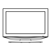
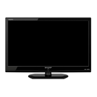
Identifies key external parts of the TV unit and its rear panel.

Remote Control Unit Functions

Explains the function of each button on the remote control unit.

ATTACHING THE TV STAND

Stand Attachment Procedure

Step-by-step instructions for safely attaching the TV stand to the unit.

CHAPTER 4. DIMENSIONS

TV External Dimensions

Diagrams illustrating the external physical dimensions of the TV in millimeters.

CHAPTER 5. REMOVING MAJOR PARTS

Removing Rear Cabinet and Stand Base

Instructions for detaching the rear cabinet assembly and the stand base.

Removing Bottom Bracket and PWB Chassis

Steps to remove the bottom bracket, speakers, and PWB chassis.

Removing the LCD Panel Unit

Procedures for safely disconnecting and removing the LCD panel unit.

CHAPTER 6. ADJUSTMENT PROCEDURES

Entering and Exiting Adjustment Mode

Steps to enter, operate within, and cancel the adjustment mode.

TV Signal and Picture Adjustment

Details on EDID data and signal adjustments, including picture calibration.

Adjustment Modes and Settings

Covers various adjustment modes and specific procedures for signal settings.

WHITE BALANCE ADJUSTMENT

White Balance Adjustment Setup and Procedure

Details on setting up and performing white balance adjustments.

White Balance Calibration Calculations

Provides detailed calculation steps and reference values for white balance calibration.

FACTORY SETTING PROCEDURES

Performing Factory Settings

Describes the process and initializations for factory setting the TV.

CHAPTER 7. TROUBLESHOOTING

Troubleshooting: No Power Issues

Guide for diagnosing and resolving power-related problems.

Troubleshooting: No Video (RF Signal)

Flowchart for diagnosing no video issues when using RF signal input.

Troubleshooting: No Video (ComponentHDMI)

Flowcharts for diagnosing no video issues with component and HDMI inputs.

Troubleshooting: No Audio (UHFVHF Reception)

Steps to diagnose no audio for UHF/VHF reception.

Troubleshooting: No Audio (External Inputs)

Guide for diagnosing no audio from external AV and component inputs.

Troubleshooting: No Audio (HDMI Input)

Steps to diagnose no audio issues specific to HDMI signal input.

CHAPTER 8. SYSTEM BLOCK DIAGRAM

Overall System Block Diagram

Illustrates the interconnected components and signal flow of the TV system.

CHAPTER 9. PRINTED BOARD ASSEMBLIES

Main Unit PWB Layouts

Shows component layouts for Main PWB Sides A, B, and Chip.

LED RC Unit PWB Layouts

Shows component layouts for LED RC PWB Sides A, B, and Chip.

Power Unit PWB Layouts

Shows component layouts for Power PWB Sides A, B, and Chip.

CHAPTER 10. SCHEMATIC DIAGRAMS

Main Unit Schematic Diagram

Detailed schematic for the Main Unit.

LED RC Unit Schematic Diagram

Detailed schematic for the LED RC Unit.

Power Unit Schematic Diagram

Detailed schematic for the Power Unit.

SHARP PARTS GUIDE

Parts Guide Index

Overview and index of parts listed in the guide.

Printed Wiring Boards & LCD Panel Parts

Parts list for PWBs and the LCD panel.

Main Unit Parts Detailed List

Comprehensive list of components for the Main Unit.

Power Unit & LEDRC Unit Parts List

Parts list for the Power and LED/RC Units.

Cabinet and Mechanical Parts

Lists and diagrams cabinet and mechanical components.

Supplied Accessories List

Lists included accessories like remote, batteries, and manuals.

PACKING AND SHIPPING INFORMATION

Packing Parts Diagram and List

Illustrates and lists the packing materials for shipping.

COPYRIGHT AND PRODUCTION INFO

Manual Copyright and Production Details

Contains copyright notices and manufacturing information for the manual.

Related product manuals