DISASSEMBLY INSTRUCTIONS
B1-1
1. REMOVAL OF MECHANICAL PARTS
AND P.C. BOARDS
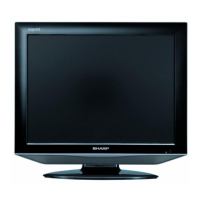
1-1: COVER BACK/STAND ASS'Y (Refer to Fig. 1-1)
1.
2.
3.
4.
5.
6.
7.
8.
Unlock the 2 supports 1.
Remove the Cover Back in the direction of arrow (A).
Remove the 3 screws 2.
Remove the Stand Ass'y in the direction of arrow (B).
Remove the 5 screws 3.
Remove the Frame Stand in the direction of arrow (C).
Remove the 4 screws 4.
Remove the Angle Stand in the direction of arrow (D).
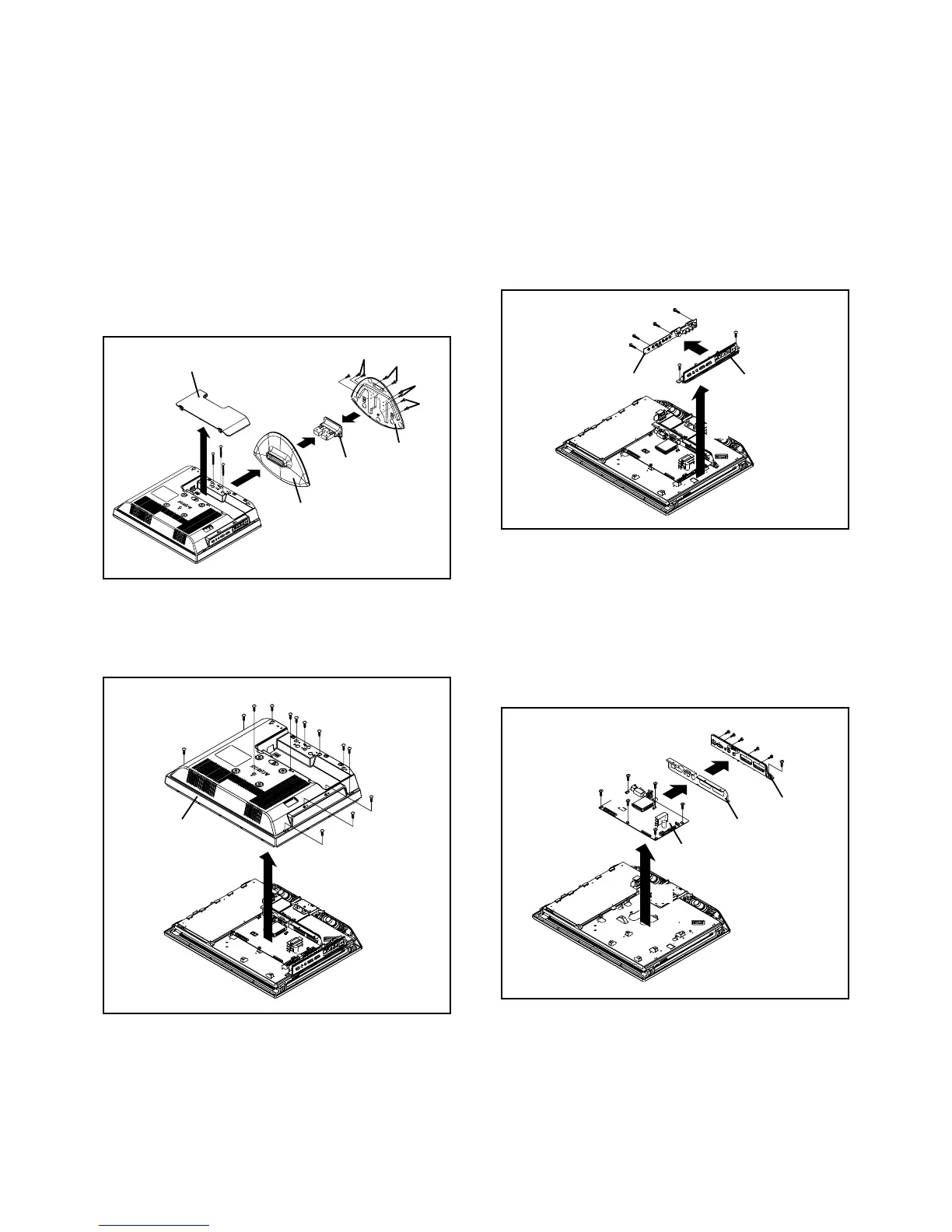
1-3: OPERATION PCB (Refer to Fig. 1-3)
1.
2.
3.
4.
5.
Disconnect the following connectors:
(CP301 and CP4201).
Remove the 2 screws 1.
Remove the Plate Button Ass'y in the direction of arrow
(A).
Remove the 4 screws 2.
Remove the Operation PCB in the direction of arrow
(B).
Fig. 1-3
1-2: BACK CABINET (Refer to Fig. 1-2)
1.
2.
3.
Remove the 9 screws 1.
Remove the 4 screws 2.
Remove the Back Cabinet in the direction of arrow.
Fig. 1-2
Fig. 1-1
Cover Back
Stand
(A)
2
2
1
1
(B)
2
4
3
(C)
(D)
Angle Stand
Frame Stand
3
3
4
Back Cabinet
2
1
1
1
1
1
1
1
1
1
2
2
2
1-4: MAIN PCB (Refer to Fig. 1-4)
1.
2.
3.
4.
5.
6.
7.
Disconnect the following connectors:
(CP302, CP3400, CP3401, CP4301 and CP7201).
Remove the 7 screws 1.
Remove the Main PCB in the direction of arrow (A).
Remove the 2 screws 2.
Remove the 3 screws 3.
Remove the Plate Jack in the direction of arrow (B).
Remove the Shield Jack in the direction of arrow (C).
1
Operation PCB
2
1
2
2
2
Plate Button Ass'y
(B)
(A)
1
Main PCB
Fig. 1-4
1
1
1
1
1
Shield Jack
Plate Jack
2
1
2
3
3
3
(A)
(B)
(C)