Do you have a question about the Sharp LC-26D44 and is the answer not in the manual?
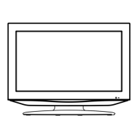
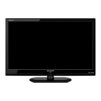
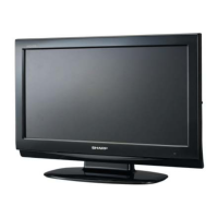
Describes screen sizes (26", 32") and cabinet features like bottom speakers and color.
Lists specific model designations for Continental, Sweden, UK, and Russian markets.
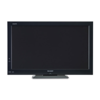
Highlights main attributes like ASV LCD, HD Ready, wide viewing angle, and built-in tuner.
Comprehensive table listing panel, resolution, video/audio systems, and terminals.
Details the COFDM Decoder (IC207) and HDMI Receiver (IC1951) integrated circuits.
Covers Digital Processor, NVM, EEPROM, CPU, and peripheral ICs for system operation.
Details audio amplifiers, LCD controllers, NVM, I2C, and RS-232 transceiver ICs.
Overall wiring diagrams and specific block diagrams for power supply and inverter circuits.
Outlines methods for updating VCTPro software via RS-232C, I2C, or PCMCIA.
Describes updating the digital board software using PCMCIA card or RS-232 jig.
Step-by-step instructions to access and exit the TV's service mode.
Explains the meaning of 'K' colors and screen indicators in service mode.
Details the menu items, descriptions, and remarks for adjustment.
Procedures for adjusting tuner signal level and automatic performance.
Steps for White Balance adjustment using a PC and RS-232 commands.
Guides for entering and configuring Hotel Mode settings.
Configuration options for public display mode.
Schematics for tuner, OFDM, video inputs, terminals, HDMI, and RS232.
Diagrams for DTV decoder, memory, CI, and VCT-PRO ATV CPU.
Circuits for audio amplifier, LCD controller, T-CON, and UCON/Panel-IF.
Detailed diagrams of power supply and inverter stages for 26" and 32" models.
Visual layout of the main printed circuit boards (Side A and Side B).
Layouts for Mini-AV, Key, and LED control printed circuit boards.
Visual layout of the 26" and 32" power supply and inverter boards.
| Screen Size | 26 inches |
|---|---|
| Resolution | 1366 x 768 |
| Display Type | LCD |
| Aspect Ratio | 16:9 |
| HDMI Ports | 2 |
| Component Video Inputs | 1 |
| Composite Video Inputs | 1 |
| Weight | 11.9 kg |
| Contrast Ratio | 1200:1 |
| Brightness | 450 cd/m² |
| Viewing Angle | 176° |
| Input Ports | HDMI, Component, Composite |
| Sound Output | 10W x 2 |
| Audio Output | 2 x 5W |