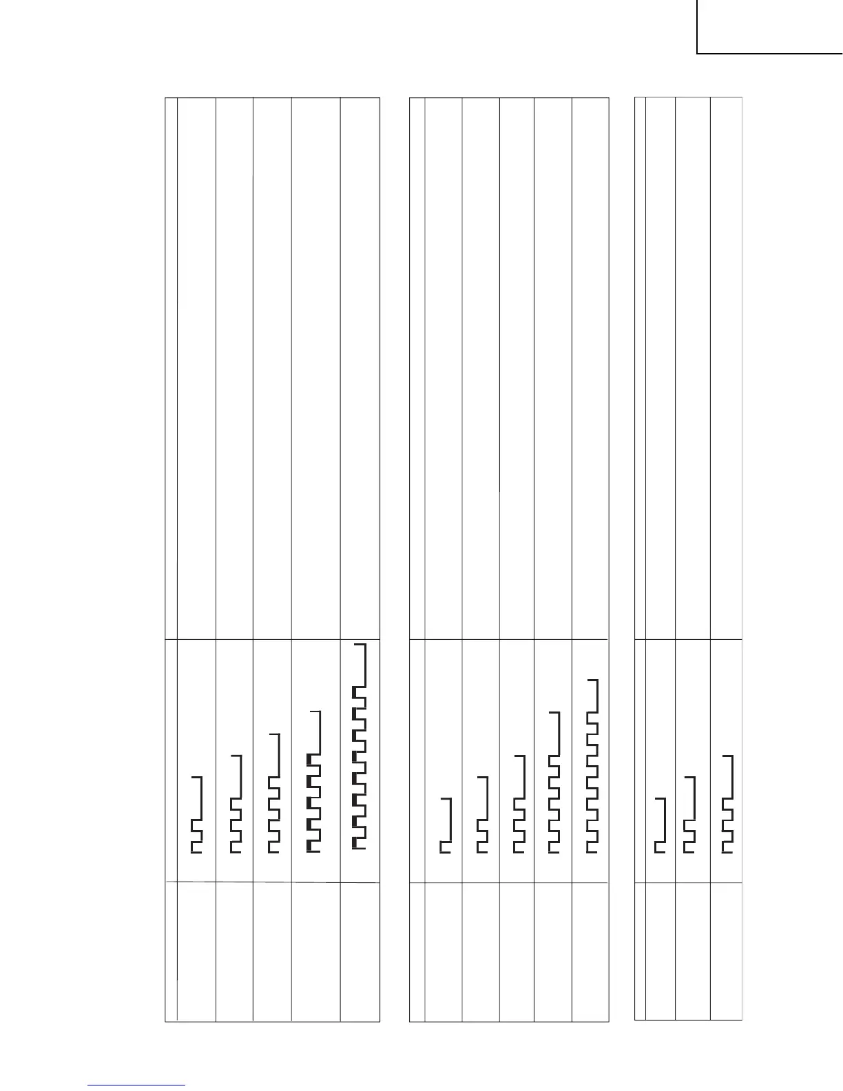
LED flashing timing chart for error notification
1) Red power LED
Remarks
Remarks
Remarks
Error type Power red LED operation (1 cycle)
Error type Power red LED operation (1 cycle)
Error type Power red LED operation (1 cycle)
Pins are monitor microprocessor pins.
H: On
L: Off
H: On
L: Off
H: On
L: Off
H: On
L: Off
H: On
L: Off
H: On
L: Off
H: On
L: Off
H: On
L: Off
H: On
L: Off
H: On
L: Off
H: On
L: Off
H: On
L: Off
Refer to "Power failure details".
Power failure
Flashes twice
communication failure
Refer to "Communication failure details".
with main CPU
Communication line failure or main CPU communication failure > Check debug statements for the main CPU.
Flashes 3 times
Vsync
failure
Flashes 4 times
Monitor temperature failure
Flashes 5 times
2) Power failure details (Power LED flashes twice and OPC LED flashes)
Pins are monitor microprocessor pins unless otherwise specified.
DET_10V failure
Flashes once
DET_D3.3V failure
Flashes twice
DET_6V failure
Flashes 3 times
Panel 5V failure
Flashes 5 times
Main failure
Flashes 7 times
3) Communication failure details (Power LED flashes 3 times and OPC LED flash
Initial communication
reception failure
Flashes once
Time-out setting reception failure
Start-up confirmation reception failure
Flashes twice
Regular communication failure
Flashes 3 times
The details are displayed in "ERROR STANDBY CAUSE" on page 1 of process A mode for the main microprocessor.
Initial communication from the main CPU is not received. (After canceling the reset, request for the monitor model No. is not received.)
→
Communication line failure or main CPU start-up failure
Time-out setting and start-up mode change cannot be received from the main CPU. (Start-up communication until time-out setting and
startup mode change is not received.)
Basically, communication logs are analyzed by a bus monitor or debug print logs are analyzed.
→
Main CPU start-up failure or monitor microprocessor's reception failure
Regular communication that is performed at 1 second intervals in the normal operation is interrupted.
→
Main CPU operation failure or monitor microprocessor's reception failure
Main microprocessor detection error,
DET_PNL5V (pin 58): Abnormal (L). Panel power is not applied.
If error is detected during operation, error standby is activated by polling.
EU_POW
PS_ON
PANEL_POW
D_POW
If error is detected during operation, error standby is activated by polling.
DET_6V (pin 56): Abnormal (L). D5V,A5V is not applied.
(MONITOR MAX TEMP on process A mode: Change of temperature failure AD value): Thermistor
If error is detected during operation, error standby is activated by polling.
AC_DET (pin 16): Abnormal (L), DET_10V (pin 57). Main converter A9V/UR10V is not applied.
If error is detected during operation, the power is turned on again by interrupt handling (instantaneous blackout processing).
DET_3V3 (pin 59): Abnormal (L). Main power 3.3V is not applied.
VSYNC (pin 46) failure (uninput). Video process operation failure.
Detected during operation (interruption)
If the panel temperature is 60˚C or more for 15 seconds or more in a row, CAUTION appears on the OSD of AVC (flashes in red in the
lower right screen).
If the panel temperature is 60˚C or more for 25 seconds or more in a row, error standby is activated.
MAIN CPU communication: TXD(28pin),RXD(29pin).
H: On
L: Off
Program DATA broken
Flaches & times.
Recovery: Mcu flash ROM DATA failure.
Mcu SOFT rewrite.