Do you have a question about the Sharp LC-26AF3 M/H/X and is the answer not in the manual?
Safety warnings for continued service, including circuit modification and power disconnection.
Safety checks required before returning the receiver to the user, focusing on fire and shock hazards.
Notes on special safety-related characteristics of electrical and mechanical parts.
Information on the use of lead-free solder, indicated by the LF symbol.
Guidance on selecting and using lead-free wire solder for repairs.
Precautions and best practices for soldering with lead-free solder.
Key display parameters including size, resolution, brightness, and viewing angles.
Details on TV reception, audio output, and speaker configuration.
Information on power, weight, operating conditions, and input/output terminals.
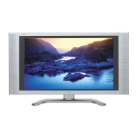
Overview of the TV's front and rear panels, including controls and connections.
Details on indicators, sensors, and reset operations for the TV.
Detailed explanations of the functions of each remote control button.
Specific functions related to TELETEXT mode on the remote control.
Guides for connecting VCRs, DVD players, and other audiovisual equipment.
Instructions on selecting input sources and signal types for external equipment.
Instructions for connecting an HDTV tuner to the TV.
Guidance on connecting game consoles and camcorders.
Common problems and their possible solutions for operating the TV.
Precautions for using the TV in high and low temperature environments.
A list of menu items available for TV operation and adjustment.
Physical dimensions and measurements for the LC-26AF3 H/M/X model.
Physical dimensions and measurements for the LC-32/37AF3 H/M/X models.
Detailed steps for disassembling major components like covers, stand, and internal units.
Procedures for removing the LCD panel, diffusion sheets, lamp holders, and lamps.
Detailed steps for disassembling major components for specific models.
Procedures for removing the LCD panel, diffusion sheets, lamp holders, and lamps for specific models.
Notes on preparing new units with updated software after PWB or IC replacement.
Step-by-step guide for rewriting control software into the unit via an external computer.
Instructions for connecting the jig PWB to the main PWB for software rewriting.
Detailed steps for executing the program rewriting process, including software and hardware actions.
Procedures for entering and exiting the TV's adjustment process mode.
Details on remote controller key functions and display elements during adjustment.
Categorization of adjustment items such as Initialization, PAL/SECAM, HDTV, and HDMI.
Description of special features like standby cause codes, EEP save, and EEP recover.
Procedure for adjusting the COM BIAS for the LCD panel.
Steps for video signal adjustment, including signal checks and RF AGC.
Procedures for adjusting PAL, SECAM, and N358 signal parameters.
Procedures for ADC adjustments for component signals and HDMI signal adjustment.
Detailed steps for performing white balance adjustment using a luminance meter and specified reference values.
Explanation of the multiple point adjustment method for reducing color differences among gradations.
Steps to initialize the TV to factory settings, including cautions about data loss.
Instructions for entering and exiting the display adjustment mode.
Table detailing remote controller key operations within the display adjustment mode.
A list detailing the various display adjustment modes available.
Explanation of the lamp error detection feature and steps for checking and resetting the error count.
Information on key ICs for video processing, switching, and control.
Details on ICs related to LCD panel timing, memory, and LVDS communication.
Information on ICs for audio decoding, delay, and voltage generation.
Information on audio amplifier ICs and digital interface receivers for HDMI/DVI.
A wiring diagram illustrating the connections between major units for the LC-26AF3 M/H/X model.
A wiring diagram showing connections between major units for the LC-32AF3 M/H/X model.
A wiring diagram illustrating unit connections for the LC-37AF3 M/H/X model.
A high-level system block diagram illustrating the overall TV architecture.
A detailed block diagram of the main unit's components and their interconnections.
A block diagram detailing the AV unit's circuitry and signal flow.
A block diagram illustrating the power supply unit's components and functions.
A block diagram showing the inverter unit's circuitry for backlight control.
Diagrams showing component layouts for both sides of the Main Unit's printed wiring boards.
Diagrams showing component layouts for both sides of the AV Unit's printed wiring boards.
Diagrams showing component layouts for both sides of the Key Unit's printed wiring boards.
Diagrams showing component layouts for both sides of the R/C LED Unit's printed wiring boards.
Diagrams showing component layouts for both sides of the Power Unit's printed wiring boards.
Diagrams showing component layouts for Inverter Unit PWBs across different models and sides.
Details on replacement parts, safety characteristics, and how to order them.
Lists of components including PWBs, LCD panels, lamps, and integrated circuits with part numbers.
Detailed list of transistors, diodes, packaged circuits, coils, filters, and capacitors for the Main Unit.
Lists of capacitors and resistors with their part numbers, descriptions, and codes.
Continuation of the resistor list with part numbers and specifications.
Further listing of resistors with their part numbers and specifications.
Additional resistor listings including part numbers and specifications.
List of miscellaneous parts such as connectors, sockets, and heat sinks.
Lists of integrated circuits, transistors, and diodes for the AV Unit.
List of capacitors for the AV Unit with specifications.
Additional capacitor listings for the AV Unit with detailed specifications.
Further listing of AV Unit capacitors with detailed specifications.
List of resistors for the AV Unit with their part numbers and specifications.
Continuation of the AV Unit resistor list with part numbers and specifications.
Lists of integrated circuits, transistors, and diodes for the KEY Unit.
Lists of ICs, transistors, and diodes for the LC-26AF3M Inverter Unit.
Lists of transistors, capacitors, and resistors for the LC-26AF3M Inverter Unit.
Continuation of the resistor list for the LC-26AF3M Inverter Unit.
Lists of capacitors and miscellaneous parts for the LC-32AF3M Inverter Unit.
List of integrated circuits used in the Main Unit with part numbers and codes.
Lists of transistors, diodes, and capacitors for the Main Unit with detailed specifications.
List of capacitors for LC-32AF3M/H/X AV Unit with specifications.
List of resistors for LC-32AF3M/H/X AV Unit with specifications.
List of resistors for LC-37AF3M/H/X AV Unit with specifications.
Additional resistor listings for LC-37AF3M/H/X AV Unit.
List of resistors for the Power Unit with their specifications.
List of miscellaneous parts such as connectors, sockets, and heat sinks.
List of capacitors used in the Power Unit with their specifications.
Additional capacitor listings for the Power Unit with detailed specifications.
Further listing of Power Unit capacitors with specifications.
Detailed list of cabinet and mechanical parts for the LC-26AF3M/H/X model.
An exploded view diagram illustrating the assembly of cabinet and mechanical parts.
List of cabinet and mechanical parts for the LC-32AF3M/H/X model.
An exploded view diagram illustrating the assembly of cabinet and mechanical parts for the LC-32AF3M/H/X model.
List of cabinet and mechanical parts for the LC-37AF3M/H/X model.
An exploded view diagram illustrating the assembly of cabinet and mechanical parts for the LC-37AF3M/H/X model.
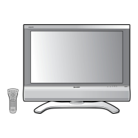
List of accessories supplied with the TV for different models.
Details on jigs and tools required for service and software upgrading.
Diagram illustrating the steps and components for packing the TV set.
Explanation of voltage measurement conditions, resistor, and capacitor notations used in schematic diagrams.
Detailed schematics for Main, AV, and Key circuits.
Detailed schematics for R/C, LED, Inverter, and Power circuits.