LC-26AF3 M/H/X
LC-32AF3 M/H/X
LC-37AF3 M/H/X
26
» Feed the PAL_Split Colour bar signal (E-12ch) to TUNER_RF.
100% white
Bring the cursor on [ËRF AGC ADJ] and press [OK].
[ËRF AGC ADJ OK] appears when finished.
8. Video signal adjustment procedure * The adjustment process mode menu is listed in Section 5.
(1) Signal check
Signal generator level adjustment check (Adjustment to the specified level)
» Composite signal NTSC : 0.714Vp-p ± 0.02Vp-p (Pedestal to white level)
» Composite signal PAL : 0.7Vp-p ±0.02Vp-p (Pedestal to white level)
» RGB signal : 0.7Vp-p± 0.02Vp-p
» 15K component signal : Y level 0.7Vp-p±0.02Vp-p (Pedestal to white level)
(50 Hz)
PB, PR level
0.7Vp-p ±0.02Vp-p
» 33K component signal : Y level 0.7Vp-p ± 0.02Vp-p (Pedestal to white level)
PB, PR leve
l 0.7Vp-p ±0.02Vp-p
(2) Entering the adjustment process mode
Enter the adjustment process mode according to Section 3.
(3) RF AGC adjustment
Adjustment point Adjustment conditions Adjustment procedure
1 Setting [Signal]
PAL_Sprit_Colour_Bar
E-12 ch, RF signal
[Terminal]
TUNER_RF
2 Auto adjustment Page 3/12
performance
7. LCD panel adjustment
COM BIAS Adjustment
Adjustment Item Adjustment conditions Adjustment procedure
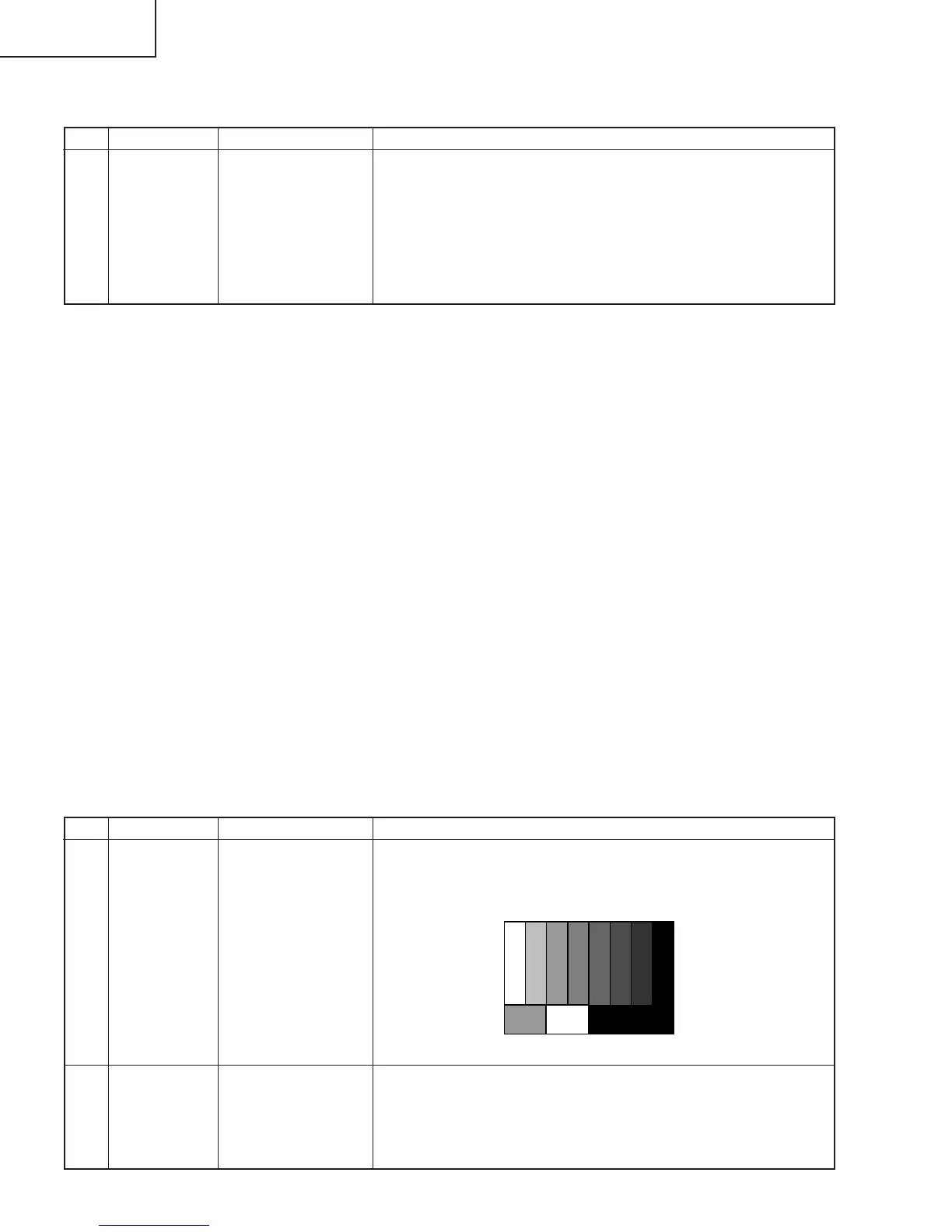
1 COM BIAS Visual inspection
1. Enter the adjustment process mode according to “11. Display
adjustment procedure”.
2. Bring the cursor (UP/DOWN) on [COMBIAS] item (11-3) and
select the value with the cursor (RIGHT/LEFT).
3. When changing values with the cursor (UP/DOWN), the test
pattern appears. Minimize the flicker in the center of the screen.
4. After minimizing the flicker, press [ENTER] of the remote control
to exit the adjustment process mode.
` Adjust COM BIAS before taking “8. Video signal adjustment procedure”.