LC-19SH7E/RU, LC-26SH7E/RU, LC-32SH7E/RU, LC-42SH7E/RU
110
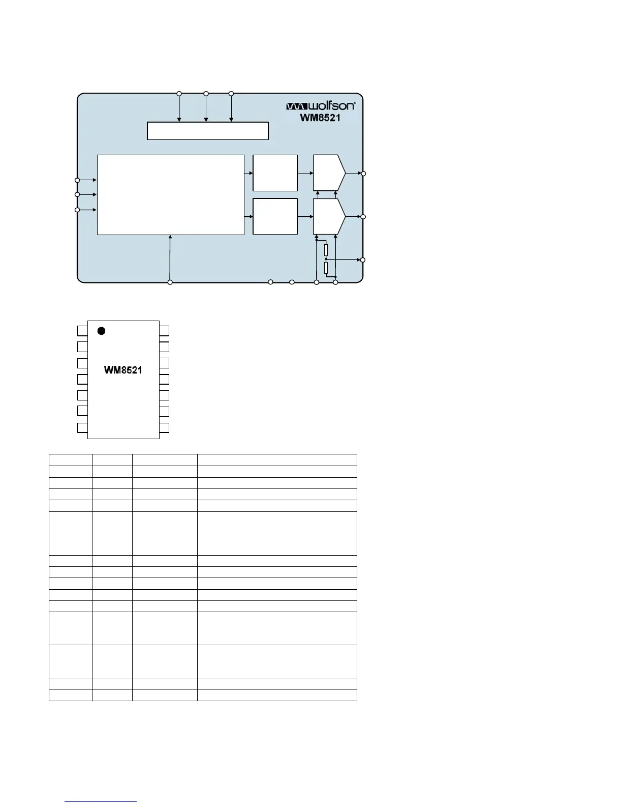
2.4. U602 (WM8521H9GED/RV SOIC-14)
2.4.1 Block Diagram
2.4.2 Pin Connections and short description
PIN NAME TYPE DESCRIPTION
1 DGND Supply Digital Negative supply
2 LRCLK Digital input Sample rate clock input
3 DIN Digital input Serial audio data input
4 BCLK Digital input Bit clock input
5 MUTE Digital input
Soft mute control, Internal pull down
High Impedance = Automute
High = Mute ON
Low = Mute OFF
6 VOUTR Analogue output Right channel DAC output
7 AGND Supply Analogue Negative supply
8 CAP Analogue output Analogue internal reference
9 AVDD Supply Analogue Positive supply
10 VOUTL Analogue output Left channel DAC output
11 DEEMPH Digital input
De-emphasis select, Internal pull down
High = de-emphasis ON
Low = de-emphasis OFF
12 FORMAT Digital input
Data input format select, Internal pull up
Low = 16-bit right justified or 16bit DSP ‘late’
High = 16-32-bit I
2
S or 16bit DSP ‘early’
13 MCLK Digital input Master clock input
14 DVDD Supply Digital Positive supply
BCLK
LRCLK
DIN
FORMAT MUTE DEEMPH
CONTROL
INTERFACE
DIGITAL AUDIO
INTERFACE
&
DIG ITAL FILT ER S
SIGMA
DELTA
MODULATOR
RIGHT
DAC
SIGMA
DELTA
MODULATOR
LEFT
DAC
VOUTR
VOUTL
CAP
DVDD DGND AVDD AGND
1
2
3
4
5
6
7
14
13
12
11
10
9
8
DGND
LRCLK
DIN
BCLK
MUTE
VOUTR
AGND
DVDD
MCLK
FORMAT
DEEMPH
VOUTL
AVDD
CAP