EasyManua.ls Logo

Sharp LC-32D44RU-BK

Sharp LC-32D44RU-BK
142 pages
To Next Page IconTo Next Page
Loading...
SERVICE MANUAL
LC32D44E/S/RU-BK/GY (1st Eddition)
Parts marked with " " are important for maintaining the safety of the set. Be sure to replace these parts with specified ones for maintaining the
safety and performance of the set.
This document has been published to be used for
after sales service only.
The contents are subject to change without notice.
SAFETY PRECAUTION
IMPORTANT SERVICE SAFETY PRE-
CAUTION............................................................i
PRECAUTIONS A PRENDRE LORS DE
LA REPARATION...............................................ii
PRECAUTIONS FOR USING LEAD-FREE
SOLDER ...........................................................iii
CHAPTER 1. SPECIFICATIONS
[1] SPECIFICATIONS ......................................... 1-1
[2] OPERATION MANUAL .................................. 1-2
[3] DIMENSIONS ................................................ 1-5
CHAPTER 2. REMOVING OF MAJOR PARTS
[1] REMOVING OF MAJOR PARTS ................... 2-1
CHAPTER 3. ADJUSTMENT
[1] After replacement of any PWB and/or IC for
repair, note the following. ............................... 3-1
[2] SOFTWARE UPDATING................................ 3-1
[3] Entering and exiting the adjustment pro-
cess mode.................................................... 3-18
[4] Remote controller key operation and de-
scription of display in adjustment process
mode. ........................................................... 3-18
[5] Adjustment process mode menu.................. 3-19
[6] Special features............................................ 3-20
[7] Video signal adjustment procedure.............. 3-21
[8] White Balance Adjustment........................... 3-22
[9] Adjusting procedure by use of [RS-232C]...... 3-23
[10] Initialization to factory settings.....................3-24
[11] Lamp error detection ...................................3-24
[12] Public Mode (Hotel Mode)...........................3-25
CHAPTER 4. TROUBLE SHOOTING TABLE
[1] TROUBLE SHOOTING TABLE .....................4-1
CHAPTER 5. MAJOR IC INFORMATIONS
[1] MAJOR IC INFORMATIONS .........................5-1
CHAPTER 6. BLOCK DIAGRAM/OVERALL WIRING
[1] BLOCK DIAGRAM.........................................6-1
[2] SYSTEM BLOCK DIAGRAM.........................6-3
[3] OVERALL WIRING DIAGRAM......................6-4
CHAPTER 7. PRINTED WIRING BOARD ASSEM-
BLIES
[1] MAIN Unit ......................................................7-1
[2] R/C, LED Unit................................................7-5
[3] MINI AV Unit ..................................................7-6
[4] KEY ...............................................................7-7
CHAPTER 8. SCHEMATIC DIAGRAM
[1] DESCRIPTION OF SCHEMATIC DIA-
GRAM............................................................8-1
[2] SCHEMATIC DIAGRAM................................8-2
Parts Guide
TopPage
CONTENTS
No. S38F8LC32D44E
LCD COLOUR TELEVISION
LC-32D44E/S/RU-BK/GY
MODELS
In the interests of user-safety (Required by safety regulations in some countries) the set should be restored to its orig-
inal condition and only parts identical to those specified should be used.

Table of Contents

Question and Answer IconNeed help?

Do you have a question about the Sharp LC-32D44RU-BK and is the answer not in the manual?

Sharp LC-32D44RU-BK Specifications

General IconGeneral
Screen Size32 inches
Resolution1366 x 768
Display TechnologyLCD
Aspect Ratio16:9
Brightness450 cd/m²
Response Time6 ms
HDMI Ports2
USB Ports0
VGA Port1
Display TypeTFT LCD
Viewing Angle176° (Horizontal/Vertical)
Audio Output2 x 10W
Weight11.5 kg

Summary

SAFETY PRECAUTIONS

IMPORTANT SERVICE SAFETY PRECAUTION

Essential safety guidelines for service technicians.

CAUTION: FOR CONTINUED PROTECTION AGAINST A RISK OF FIRE REPLACE ONLY WITH SAME TYPE FUSE.

Specific caution regarding fuse replacement for fire safety.

SAFETY NOTICE

Information on parts with special safety characteristics and proper replacement.

CHAPTER 1. SPECIFICATIONS

[1] SPECIFICATIONS

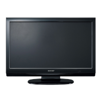
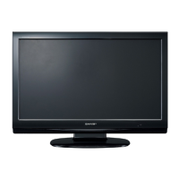
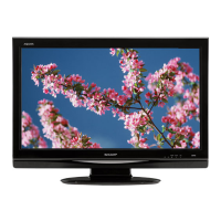
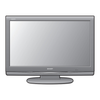
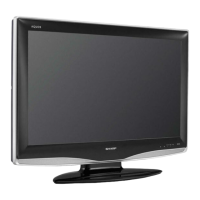
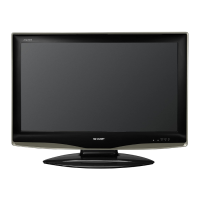
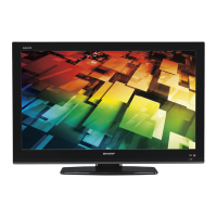
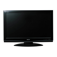
Detailed technical specifications of the LCD colour television.

Optional accessory

List of optional accessories available for the LCD colour TV.

CHAPTER 2. REMOVING OF MAJOR PARTS

[1] REMOVING OF MAJOR PARTS

Step-by-step instructions for removing major physical components.

CHAPTER 3. ADJUSTMENT

[2] SOFTWARE UPDATING

Procedures for updating the TV's software via RS-232C or PCMCIA card.

[5] Adjustment process mode menu

Detailed menu structure and parameters for service adjustments.

[8] White Balance Adjustment

Procedure for adjusting white balance settings using specific tools.

[10] Initialization to factory settings

Procedure for resetting the TV to its original factory default settings.

[12] Public Mode (Hotel Mode)

How to enter and configure Public (Hotel) Mode settings.

CHAPTER 4. TROUBLE SHOOTING TABLE

[1] TROUBLE SHOOTING TABLE

Comprehensive guide to diagnose and resolve common TV problems.

The backlight does not light

Troubleshooting steps for issues with the TV's backlight not illuminating.

The sound is not emitted from the speaker though the picture has come out.

Diagnostic steps for audio output problems when video is present.

No picture on the display (1)

Troubleshooting steps for display issues across all input modes.

CHAPTER 5. MAJOR IC INFORMATIONS

[1] MAJOR IC INFORMATIONS

Detailed information on the major integrated circuits used in the TV.

CHAPTER 6. BLOCK DIAGRAMOVERALL WIRING

[1] BLOCK DIAGRAM

Visual representation of the TV's internal circuitry and signal flow.

[2] SYSTEM BLOCK DIAGRAM

Overview of the TV's system architecture and component interconnections.

[3] OVERALL WIRING DIAGRAM

Diagram illustrating the physical wiring and connections between units.

CHAPTER 7. PRINTED WIRING BOARD ASSEMBLIES

[1] MAIN UNIT

Layout diagrams for the main circuit board (both sides).

[4] DUNTKE449 FM02 (MAIN Unit)

Parts list for the main unit assembly.

[7] CABINET PARTS

List of part numbers for cabinet components and accessories.

[8] LCD MODULE ASSEMBLY

List of part numbers for the LCD module assembly components.

[9] SUPPLIED ACCESSORIES

List of supplied accessories like remote, cables, and manuals.

CHAPTER 8. SCHEMATIC DIAGRAM

[1] DESCRIPTION OF SCHEMATIC DIAGRAM

Explanations of symbols, voltage measurements, and component indications.

[2] SCHEMATIC DIAGRAM

Detailed circuit schematics for the television's main unit and sub-units.

Power Inverter Unit

RUNTA395 WJQZ Power Supply & Inverter Block Diagram (26)

Block diagram illustrating the power supply and inverter unit functions.

PARTS GUIDE

[1] PRINTED WIRING BOARD ASSEMBLIES

List of part numbers for printed wiring board assemblies.

[4] DUNTKE449 FM02 (MAIN Unit)

Parts list for the main unit assembly.

[7] CABINET PARTS

List of part numbers for cabinet components and accessories.

[8] LCD MODULE ASSEMBLY

List of part numbers for the LCD module assembly components.

[9] SUPPLIED ACCESSORIES

List of supplied accessories like remote, cables, and manuals.

[10] PACKING PARTS

[10] PACKING PARTS

List of parts included in the product packaging.

[11] SERVICE JIGS

[11] SERVICE JIGS

List of special jigs used for service and maintenance.

Related product manuals