LC-32/40/46/52LE700UN
4 – 7
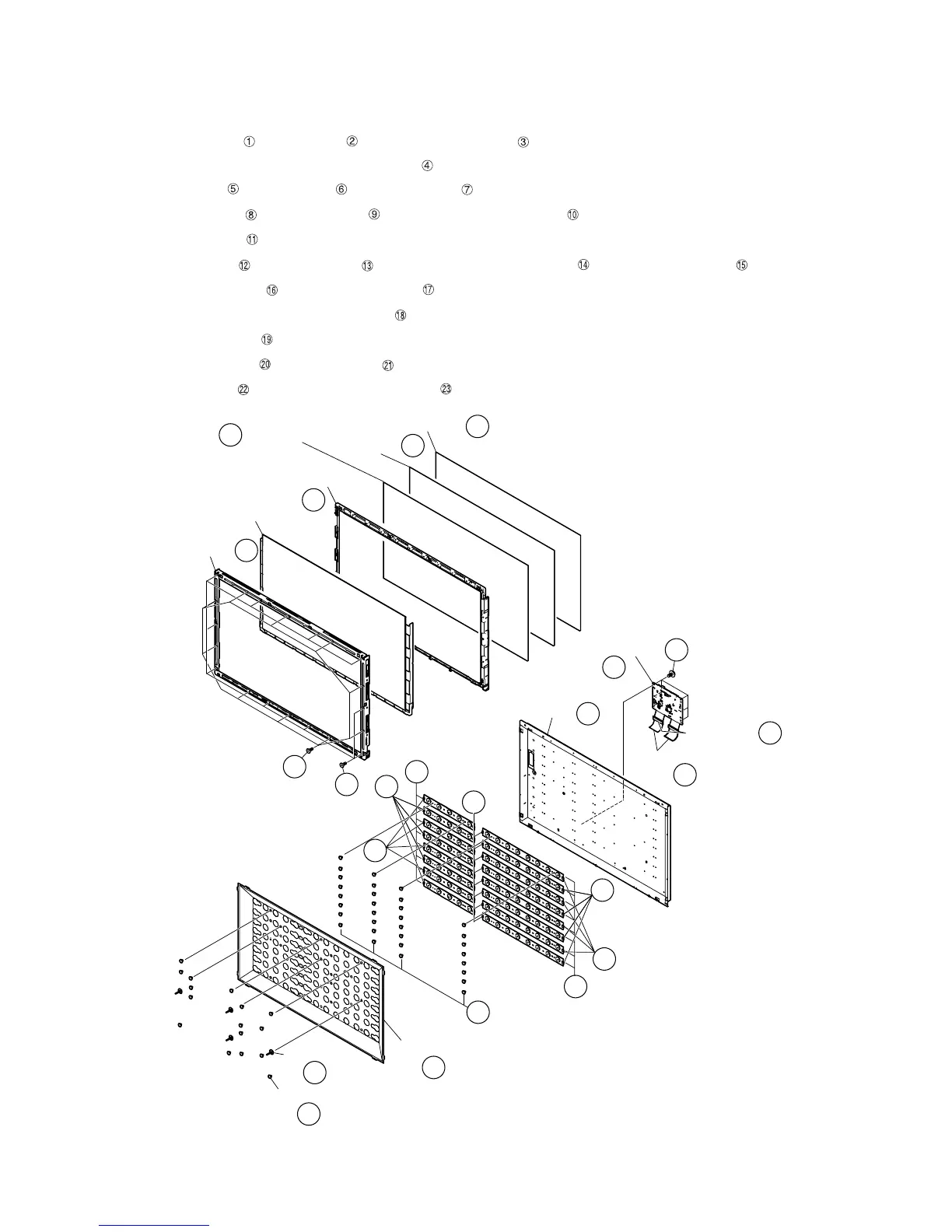
6. Removing of Bezel Ass’y, Panel Chassis Ass’y, Optical Sheet, Lens Sheet, Diffusion Plate, Back Light Chas-
sis and LCD Control Unit (LC-32LE700UN).
NOTE: A clean booth is required for repair of the component units and/ or parts (LCD Panel HIRAKI, LED PWB etc.) inside the LCD panel module
unit.
1. Remove the 10 lock screws ,10 lock screws and detach the Bezel Ass’y .
2. Detach the 32” LCD Panel Module and Panel Chassis Ass’y .
3. Detach the Optical sheet and Lens Sheet and Diffusion Plate .
4. Remove the 16 Push Rivets and 4 Support Pins and detach the Reflection Sheet .
5. Remove the 32 Push Rivets .
6. Remove the 8 Terminators and 8 connections and detach the 4 LED8 PWB1 Units and 4 LED8 PWB2 Units .
7. Detach the 4 LED5 PWB1 Units and 4 LED5 PWB2 Units .
8. Disconnect the connecting cords from the 8 connectors of the LED5 PWB1/2 Unit.
9. Detach the Back Light Chassis .
10.Detach the 2 Connecting Cord and 2 Ferrite Core .
11.Remove the 6 lock screws and detach the LCD Control Unit
䎳䏄䏑䏈䏏䎃䎃䎦䏋䏄䏖䏖䏌䏖䎃
䎤䏖䏖䎊䏜
䎖䎕䎅䎃䎯䎦䎧
䎳䏄䏑䏈䏏䎃䎸䏑䏌䏗
䎥䏈䏝䏈䏏䎃䎤䏖䏖䎊䏜
䎯䏈䏑䏖䎃䎶䏋䏈䏈䏗
䎲䏓䏗䏌䏆䏄䏏䎃䎶䏋䏈䏈䏗
䎧䏌䏉䏉䏘䏖䏌䏒䏑䎃䎳䏏䏄䏗䏈
䎵䏈䏉䏏䏈䏆䏗䏌䏒䏑䎃䎶䏋䏈䏈䏗
䎶䏘䏓䏓䏒䏕䏗䎃䎳䏌䏑
䎳䏘䏖䏋䎃䎵䏌䏙䏈䏗
䎔
䎕
䎖
䎗
䎘
䎙
䎚
䎜
䎛
䎔䎓
䎔䎔
䎔䎗
䎔䎕
䎔䎖
䎔䎘
䎔䎙
䎔䎚
䎔䎛
䎔䎜
䎕䎓
䎕䎔
䎥䏄䏆䏎䎃䎯䏌䏊䏋䏗䎃
䎦䏋䏄䏖䏖䏌䏖
䎩䏈䏕䏕䏌䏗䏈䎃䎦䏒䏕䏈
䎦䏒䏑䏑䏈䏆䏗䏌䏑䏊䎃䎦䏒䏕䏇
䎯䎦䎧䎃䎦䏒䏑䏗䏕䏒䏏䎃
䎸䏑䏌䏗
䎕䎖
䎕䎕

 Loading...