LC-32/40/46LE705E/S, LU705E/S, LX705E, LC-52LE705E/S
1 – 3
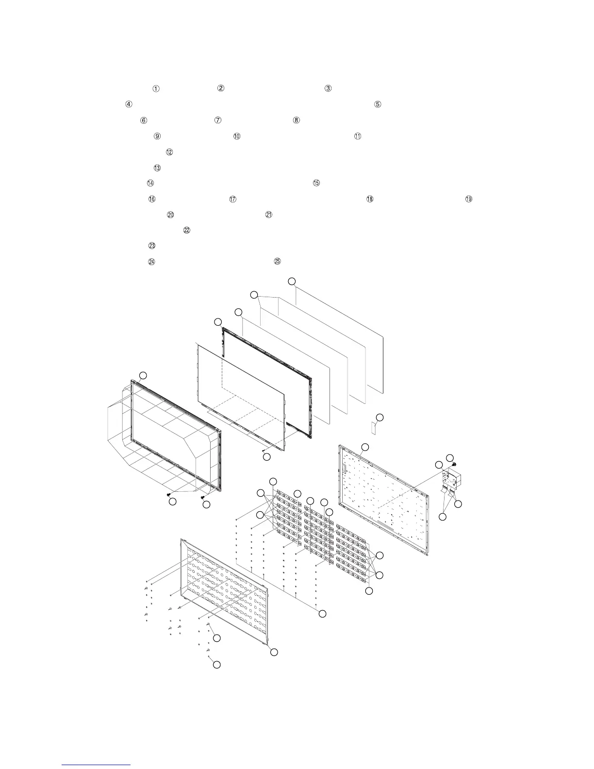
3. Removing of Bezel Ass’y, Panel Chassis Ass’y, Lens Sheet, Diffusion Plate, Back Light Chassis and LCD
Control Unit (40 inch models).
NOTE: A clean booth is required for repair of the component units and/ or parts (LCD Panel HIRAKI, LED PWB etc.) inside the LCD panel module
unit.
1. Remove the 14 lock screws ,12 lock screws and detach the Bezel Ass’y .
2. Remove the 4 Clips and detach the 40” LCD Panel HIRAKI Unit and Panel Chassis Ass’y .
3. Detach the DBEF Sheet and 2 Lens Sheet and Diffusion Plate .
4. Remove the 20 Push Rivets and 8 Support Pins and detach the Reflector Sheet .
5. Detach the 2 Connection Cords .
6. Remove the 42 Push Rivets .
7. Detach the Bush Cap Unit and connecting cords from the 7 Connectors of the LED5-PWB1/2 Unit.
8. Remove the 7 Terminators and 14 connections and detach the 8 LED6-PWB1 Units and 6 LED6-PWB2 Units .
9. Detach the 4 LED5-PWB1 Units and 3 LED5-PWB2 Units .
10.Detach the Back Light Chassis Ass’y .
11.Detach the 2 Ferrite Cores .
12.Remove the 6 lock screws and detach the LCD Control Unit .
2
3 Bezel Ass'y
40" LCD Panel HIRAKI Unit
Panel Chassis Ass'y
Clip4
Support Pin10
Push Rivet9
Reflector Sheet11
13
1
5
DBEF Sheet 6
Lens Sheet 7
Diffusion Plate 8
18
19
22
16
18
20
19
Back Light Chassis Ass'y
14 Bush Cap Unit
25LCD Control Unit
12 Connecting Cord
23
24
Ferrite Core
21
15
17
17