LC-32M400M-BK/WH/RD
2 – 1
LC32M400MBK
Service Manual
CHAPTER 2. OPERATION MANUAL
[1] OPERATION MANUAL
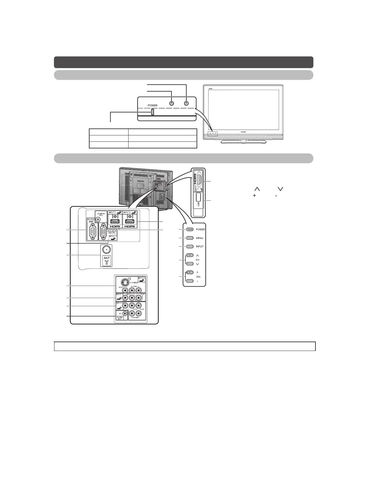
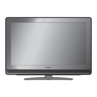
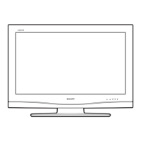
Part names
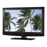
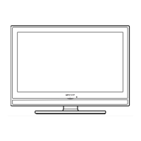
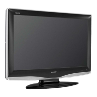
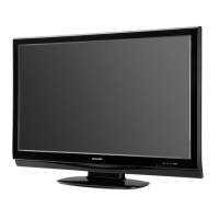
TV (Front)
OPC sensor
POWER indicator
Light off Power off
Lighted (Red) The TV is in standby mode.
Lighted (Green) The TV is on.
TV (Rear)
6
7
8
9
11
12
10
14
13
15
16
1
2
3
4
5
1POWER(On/Off) button
2MENUbutton
3INPUTbutton
4 Channel up ( )/down ( ) buttons
5 Volume up ( )/down ( ) buttons
6 RS-232C terminal
7INPUT 7 (PC) terminals*
8 Antenna input terminal
9 INPUT 4 terminals
10 INPUT 5 terminals
11 INPUT 6 terminals
12 AUDIO OUT terminal
13 INPUT 2 (HDMI) terminal
14 INPUT 1 (HDMI) terminal*
15 INPUT 3 (HDMI) terminal
16 USB terminal
* The INPUT 1 and INPUT 7 terminals can both use the same audio input terminal. However, the proper item must be
selected in the “PC Audio Select” menu.
• The illustrations in this operation manual are for explanation purposes and may vary slightly from the actual operations.
Remote control sensor