Do you have a question about the Sharp LC-32M400M-BK and is the answer not in the manual?
Essential safety guidelines for service technicians, including warnings and hazard prevention.
Procedures to prevent fire and electric shock hazards before returning the unit.
Information regarding special safety-related characteristics of electrical and mechanical parts.
Guidelines for using and identifying lead-free solder on PWBs and service manuals.
Instructions and recommendations for using lead-free wire solder for repairs.
List of main service parts including PWB units, other units, ICs, and service jigs.
Detailed technical specifications of the LCD Colour Television model.
Description of TV front and rear panel controls, power indicator, and remote control functions.
Instructions for controlling the TV from a PC using RS-232C communication.
Detailed list of commands and parameters for RS-232C TV control.
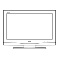
Detailed physical dimensions of the TV set, shown in millimeters.
Procedure to detach the stand unit and rear cabinet assembly.
Instructions for disconnecting various internal unit connectors for disassembly.
Steps to remove the side AV cover, speakers, and bottom bracket.
Procedure for detaching the Printed Wiring Board (PWB) units.
Method for safely removing the LCD panel module from the front cabinet.
How to enter, operate, and exit the TV's adjustment process mode.
Procedure for upgrading the TV's software using a USB device.
Steps for adjusting video signals, including composite, component, and PC inputs.
Procedure for adjusting white balance using specific test equipment and settings.
Steps to reset the TV to its factory default settings.
Using the Smart Loader function to replicate user settings between TVs via USB.
Guide to entering, exiting, and setting values in the TV's public mode.
Flowchart for diagnosing and resolving power-on and startup problems.
Troubleshooting steps for no video display across various input signals.
Diagnostic procedures for identifying and fixing audio issues for different inputs.
Diagram showing the interconnection of major units and their respective connectors.
High-level functional block diagram illustrating the TV's internal system architecture.
Component layout diagram for the MAIN Unit's printed wiring board (Side-A).
Component layout diagram for the IR/OPC Unit's printed wiring board.
Component layout diagram for the TERMINAL Unit's printed wiring board.
Explanation of resistor, capacitor indications, and safety notes for schematic diagrams.
Detailed schematics for the MAIN Unit.
Schematic diagram for the IR/OPC Unit, showing RC/LED control.
Schematics for the TERMINAL Unit, detailing interface connections and keys.
Diagrams and part codes for cabinet, mechanical components, and screws.
List and images of items supplied with the television, including remote, batteries, and manuals.
List of packing materials and labels used for product packaging.
List of specific cables and jigs required for servicing operations.