EasyManua.ls Logo

Sharp LC-32A33T

Sharp LC-32A33T
38 pages
To Next Page IconTo Next Page
Loading...
SERVICE MANUAL
Parts marked with " " are important for maintaining the safety of the set. Be sure to replace these parts with specified ones for maintaining the
safety and performance of the set.
This document has been published to be used for
after sales service only.
The contents are subject to change without notice.
OUTLINE AND DIFFERENCES FROM BASE MODEL
OUTLINE.................................................................... i
DIFFERENCES FROM BASE MODEL...................... i
SAFETY PRECAUTION
IMPORTANT SERVICE SAFETY
PRECAUTION...........................................................iii
PRECAUTIONS FOR USING LEAD-FREE
SOLDER .................................................................. iv
CHAPTER 1. SPECIFICATIONS
[1] SPECIFICATIONS .................................................1-1
CHAPTER 2. OPERATION MANUAL
[1] OPERATION MANUAL ..........................................2-1
CHAPTER 3. DIMENSIONS
[1] DIMENSIONS (LC-32A33T)...................................3-1
[2] DIMENSIONS (LC-37A33T)...................................3-2
CHAPTER 4. REMOVING OF MAJOR PARTS
[1] REMOVING OF MAJOR PARTS (LC-32A33T)......4-1
[2] REMOVING OF MAJOR PARTS (LC-37A33T)......4-6
CHAPTER 5. SCHEMATIC DIAGRAM
[1] DESCRIPTION OF SCHEMATIC DIAGRAM .........5-1
[2] MAIN Unit...............................................................5-2
Parts Guide
TopPage
CONTENTS
In the interests of user-safety (Required by safety regulations in some countries) the set should
be restored to its original condition and only parts identical to those specified should be used.
LCD COLOUR TELEVISION
No. SY8T8LC37A33T
LC-32/37A33T
LC-32A33T
LC-37A33T
MODELS
OUTLINE
This model is based on the LC-32A33M and is changed some parts. This Service Manual covers the modifications
alone. For the other points, refer to the LC-32A33M (No. SY7B8LC32A33M) Service Manual.
Question and Answer IconNeed help?

Do you have a question about the Sharp LC-32A33T and is the answer not in the manual?

Sharp LC-32A33T Specifications

General IconGeneral
Screen Size32 inches
Display TechnologyLCD
Aspect Ratio16:9
Brightness450 cd/m²
Response Time6.5 ms
Speakers10W x 2
Resolution1366 x 768
Viewing Angle176°
TV TunerAnalog
Input PortsHDMI

Summary

Manual Scope and Model Differences

Differences from Base Model (LC-32 A33 T)

Lists changes in parts for LC-32A33T compared to the base model.

List of Changed Parts (LC-37 A33 T)

Details part changes specific to the LC-37A33T model.

Safety Precautions

Important Service Safety Precautions

Guidelines for qualified technicians performing service work.

Receiver Return Safety Checks

Safety checks before returning the unit to the user.

Safety Notice

Importance of safety-related parts and using specified replacements.

Precautions for Using Lead-Free Solder

Employing Lead-Free Solder

Information about lead-free solder and its markings (LF symbol).

Using Lead-Free Wire Solder

Guidance on using lead-free wire solder and soldering bits.

Soldering Techniques

Techniques and precautions for soldering with lead-free solder.

Chapter 1: Specifications

Specifications

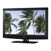
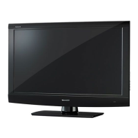
Detailed technical specifications for LC-32A33T and LC-37A33T models.

Chapter 2: Operation Manual

Operation Manual Overview

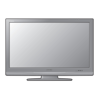
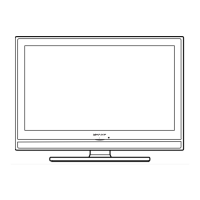
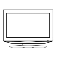
Explains preparation and part names for front controls.

Chapter 3: Dimensions

Dimensions (LC-32 A33 T)

Technical drawing showing dimensions for the LC-32A33T model.

Dimensions (LC-37 A33 T)

Technical drawing showing dimensions for the LC-37A33T model.

Chapter 4: Removing of Major Parts

Removing Stand Assy and Rear Cabinet (LC-32 A33 T)

Steps to remove the stand assembly and rear cabinet for LC-32A33T.

Removing Speakers, Bottom Cover and Stand Angle (LC-32 A33 T)

Steps to remove speakers, bottom cover, and stand angle.

Removing of Connecting Cord (LC-32 A33 T)

Instructions for disconnecting various cables and cords.

Removing of PWB Units (LC-32 A33 T)

Steps to remove the R/C, KEY, INVERTER/POWER, and MAIN PWB units.

Removing of Center Angle and LCD Angle-AB (LC-32 A33 T)

Steps to remove center and LCD angles before detaching the LCD panel.

Removing Stand Assy and Rear Cabinet (LC-37 A33 T)

Steps for removing major parts specific to the LC-37A33T model.

Removing Speakers, Bottom Cover and Stand Angle (LC-37 A33 T)

Steps to remove speakers, bottom cover, and stand angle for LC-37A33T.

Removing of Connecting Cord (LC-37 A33 T)

Instructions for disconnecting cords for the LC-37A33T.

Removing of PWB Units (LC-37 A33 T)

Steps to remove PWB units for the LC-37A33T.

Removing of Center Angle and LCD Angle-AB (LC-37 A33 T)

Steps to remove angles for the LC-37A33T LCD panel.

Chapter 5: Schematic Diagram

Description of Schematic Diagram

Explains voltage measurement conditions and component indications.

Main Unit Schematic

Schematic diagram for the MAIN Unit.

Sharp Parts Guide

Printed Wiring Board Assemblies

List of printed wiring board assemblies and their part codes.

LCD Panel Parts

List of LCD panel part numbers.

Main Unit Parts (LC-32 A33 TLC-37 A33 T)

Specific parts listed for the MAIN Unit of both models.

Cabinet and Mechanical Parts (LC-32 A33 T)

Exploded view and parts list for cabinet and mechanical components (LC-32A33T).

LCD Panel Unit (LC-32 A33 T)

Exploded view and parts list for the LCD Panel Unit (LC-32A33T).

Cabinet and Mechanical Parts (LC-37 A33 T)

Exploded view and parts list for cabinet and mechanical components (LC-37A33T).

LCD Panel Unit (LC-37 A33 T)

Exploded view and parts list for the LCD Panel Unit (LC-37A33T).

Supplied Accessories

List of accessories supplied with the product.

Packing Parts (Not Replacement Item)

Illustration and list of packing materials.

Service Jig (For Servicing)

List of service jigs and connecting cords for servicing.

Related product manuals