EasyManua.ls Logo

Sharp LC-60E77UN User Manual

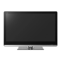
Sharp LC-60E77UN
118 pages
To Next Page IconTo Next Page
Page #1 background imageLoading...
Page #1 background image
SERVICE MANUAL
Parts marked with " " are important for maintaining the safety of the set. Be sure to replace these parts with specified ones for maintaining the
safety and performance of the set.
This document has been published to be used for
after sales service only.
The contents are subject to change without notice.
SAFETY PRECAUTION
IMPORTANT SERVICE SAFETY
PRECAUTION.....................................................i
PRECAUTIONS A PRENDRE LORS DE
LA REPARATION ...............................................ii
PRECAUTIONS FOR USING LEAD-FREE
SOLDER ........................................................... iii
CHAPTER 1. SPECIFICATIONS
[1] SPECIFICATIONS ......................................... 1-1
CHAPTER 2. OPERATION MANUAL
[1] Parts Name .................................................... 2-1
CHAPTER 3. DIMENSIONS
[1] DIMENSIONS
(LC-60E77UN/LC-C6077UN)......................... 3-1
[2] DIMENSIONS
(LC-65E77UM/LC-C6577UM) ........................ 3-2
CHAPTER 4. REMOVING OF MAJOR PARTS
[1] REMOVING OF MAJOR PARTS
(LC-60E77UN/LC-C6077UN)......................... 4-1
[2] REMOVING OF MAJOR PARTS
(LC-65E77UM/LC-C6577UM) ........................ 4-7
CHAPTER 5. ADJUSTMENT
[1] ADJUSTMENT PROCEDURE ....................... 5-1
[2]
PUBLIC MODE SETTING PROCEDURE
.......5-18
CHAPTER 6. TROUBLESHOOTING TABLE
[1] TROUBLESHOOTING TABLE ......................6-1
CHAPTER 7. MAJOR IC INFORMATIONS
[1] MAJOR IC INFORMATIONS .........................7-1
CHAPTER 8. OVERALL WIRING/SYSTEM BLOCK
DIAGRAM
[1] OVERALL WIRING DIAGRAM
(LC-60E77UN/LC-C6077UN) ........................8-1
[2] OVERALL WIRING DIAGRAM
(LC-65E77UM/LC-C6577UM) .......................8-2
[3] SYSTEM BLOCK DIAGRAM.........................8-3
CHAPTER 9. PRINTED WIRING BOARD ASSEM-
BLIES
[1] KEY Unit, R/C, LED Unit Unit ........................9-1
[2] MAIN Unit ......................................................9-2
CHAPTER 10. SCHEMATIC DIAGRAM
[1] DESCRIPTION OF SCHEMATIC
DIAGRAM....................................................10-1
[2] SCHEMATIC DIAGRAM ..............................10-2
Parts Guide
CONTENTS
No. S99C6LC60E77U
LCD COLOR TELEVISION
LC-60E77UN
LC-65E77UM
LC-C6077UN
LC-C6577UM
MODELS
In the interests of user-safety (Required by safety regulations in some countries) the set should be restored to its orig-
inal condition and only parts identical to those specified should be used.
LC-60E77UN/LC-65E77UM/LC-C6077UN/LC-C6577UM

Other manuals for Sharp LC-60E77UN

Question and Answer IconNeed help?

Do you have a question about the Sharp LC-60E77UN and is the answer not in the manual?

Sharp LC-60E77UN Specifications

General IconGeneral
BrandSharp
ModelLC-60E77UN
CategoryTV
LanguageEnglish

Summary

Safety Precautions

Important Service Safety Precautions

Key safety procedures for servicing the unit, including warnings and cautions.

Receiver Return Safety Checks

Checks to ensure safety before returning the receiver to the user.

Lead-Free Solder Usage Precautions

Guidelines and best practices for using lead-free solder during repairs.

Chapter 1: Specifications

LCD Color Television Specifications

Detailed technical specifications for the LC-60E77UN/LC-C6077UN and LC-65E77UM/LC-C6577UM models.

Chapter 2: Operation Manual

Parts Identification

Identification of external parts, connectors, and buttons on the TV.

Remote Control Unit Operation

Detailed explanation of the remote control unit's buttons and functions.

Chapter 3: Dimensions

Dimensions for LC-60E77UN/LC-C6077UN

Physical dimensions and measurements for the 60-inch models.

Dimensions for LC-65E77UM/LC-C6577UM

Physical dimensions and measurements for the 65-inch models.

Chapter 4: Removing Major Parts

Disassembly for LC-60E77UN/LC-C6077UN Models

Step-by-step instructions for removing major components from 60-inch models.

Disassembly for LC-65E77UM/LC-C6577UM Models

Step-by-step instructions for removing major components from 65-inch models.

Chapter 5: Adjustment

Adjustment Procedures

Guidance on software upgrades and VCOM adjustment.

Public Mode Setting Procedure

Instructions for accessing and configuring public mode settings.

Chapter 6: Troubleshooting Table

Troubleshooting Flowcharts

Diagnostic charts for resolving issues like no video or no audio.

Chapter 7: Major IC Information

Key Integrated Circuits Identification

List and description of major ICs used in the television system.

Chapter 8: Wiring and System Block Diagrams

Overall Wiring Diagram (60-inch Models)

Wiring diagram illustrating connections for LC-60E77UN/LC-C6077UN.

Overall Wiring Diagram (65-inch Models)

Wiring diagram illustrating connections for LC-65E77UM/LC-C6577UM.

System Block Diagram

High-level block diagram of the TV's internal system architecture.

Chapter 9: Printed Wiring Board Assemblies

Key, R/C, and LED Unit PWB Layouts

Component layout diagrams for key control and indicator boards.

Main Unit PWB Layouts

Component layout diagrams for the main circuit board (Side A and Chip Side A).

Chapter 10: Schematic Diagrams

Schematic Diagram Description and Conditions

Explanation of voltage measurement conditions and component notation.

Main Unit Schematic Diagrams

Detailed circuit diagrams for various main unit sections.
Related product manuals