LC-60/70LE660U,C6600U
5 – 8
8. Signal adjustment
8.1. LCD section adjustment [LCD module adjustment]
8.2. Image adjustment
8.2.1 Device check
Before adjustment, check that the adjustment jig and signal source are set for Sharp LCD US.
Signal generator level adjustment check (Adjust to the standard value level.)
8.2.2 Process mode
8.2.3 Component 33K signal adjustment
Adjustment item Adjustment conditions Adjustment procedure
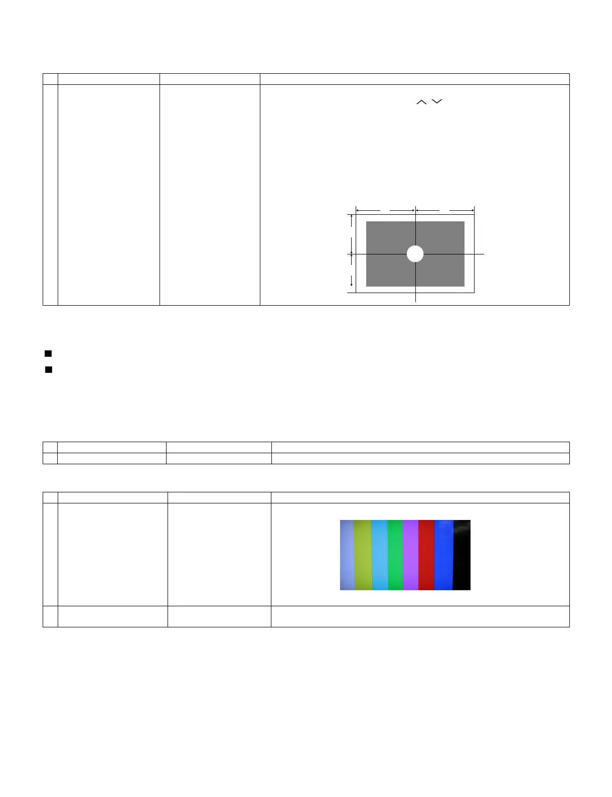
1 Opposite bias adjustment
(LCD module adjustment
item)
10/12 PANEL
Adjustment in the center
position of the panel
1) Enter the process mode using the process adjustment remote control.
2) Select [VCOM ADJ] using the Channel / keys on the remote control.
3) Press the Enter key to check that the pattern for adjustment is displayed.
4) Make adjustment so that the flicker located in the center of the screen is mini-
mized using the Volume +/- keys on the remote control.
5) If the optimum condition is obtained in step 4, press the Enter key to turn off the
pattern.
CAUTION: * Make adjustment with no ANT signal (since the brightness is changed
by the active backlight).
[Adjustment position]
• 33K component signal: Y level: 0.7Vp-p ± 0.02Vp-p (Pedestal to white)
PB/PR level: 0.7Vp-p ± 0.02Vp-p
• Analog RGB: RGB level: 0.7Vp-p ± 0.02Vp-p (Pedestal to white)
Adjustment point Adjustment conditions Adjustment procedure
Process mode Enter the process adjustment mode using the process adjustment remote control.
Adjustment point Adjustment conditions Adjustment procedure
1 Setting 1080i signal
100% FullField
ColorBar
• Send the 100% color bar signal to the component input.
2 Automatic adjustment exe-
cution
5/12 COMP HD Point the cursor to [COMP HD ADJ] and press the [Enter] key.
The adjustment is complete when [OK] is displayed.